
Through-wall masonry flashing and drainage device

a drainage device and masonry technology, applied in snow traps, wood layered products, chemistry apparatuses and processes, etc., can solve the problems of stainless steel sheet becoming thicker and harder as it is worked, flashing devices with thinner copper sheets, and becoming more susceptible to damage, etc., to achieve excellent puncture resistance, durability, and longevity.

Active Publication Date: 2014-11-25
YORK MFG
View PDF5 Cites 9 Cited by
  • Summary
  • Abstract
  • Description
  • Claims
  • Application Information

AI Technical Summary

Benefits of technology

The patent text discusses the use of copper and stainless steel sheets in flashing devices. Copper is a soft material that can easily be damaged when rolled or worked into a thinner sheet. To improve its wear resistance and durability, a reinforcing fabric is often added to the copper sheet, but this fabric can interfere with the ability to adhere air barriers and sealants to the flashing. The use of stainless steel sheets provides better puncture resistance and durability than copper, but they are more expensive. A solution is to have a reinforced stainless steel sheet with a thin layer of copper on one side, making it easier to adhere barriers and sealants. This reinforced stainless steel flashing can be shipped in a roll and formed on the jobsite, making it more versatile and user-friendly than traditional flashing.

Problems solved by technology

Due to the physical properties of copper, as it is rolled or worked into a thinner sheet, it becomes more susceptible to damage.
In doing so, the stainless steel sheet becomes thicker and harder as it is worked.
Copper flashing devices that have a thinner copper sheet therefore suffer from decreased wear resistance and reduced damage protection to the building.
Reinforcing fabric often interferes with the ability to adhere air barriers and sealants to the flashing.

Method used


Image

  • Through-wall masonry flashing and drainage device
  • Through-wall masonry flashing and drainage device
  • Through-wall masonry flashing and drainage device

Examples


Embodiment Construction

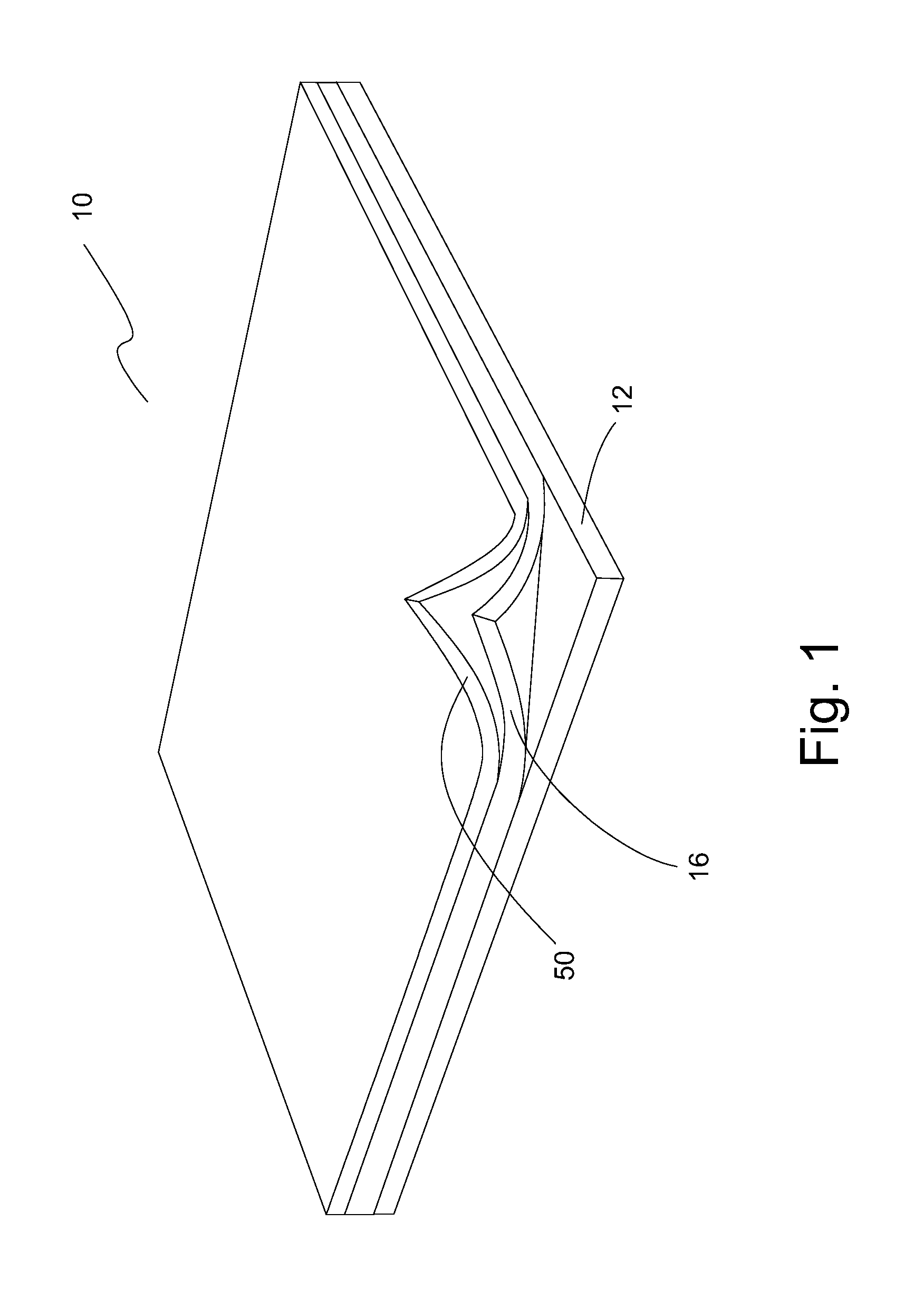
[0030]FIG. 1 shows one embodiment of a combination through-wall masonry flashing and drainage device 10 that includes a flashing membrane 12 and a wicking cloth 50 affixed to the flashing membrane 12. An optional adhesive 16 is disposed between flashing membrane 12 and wicking cloth 50. For clarity in showing the components of combination flashing and drainage device 10, the corners of adhesive16 and wicking cloth 50 are shown curled up from flashing membrane 12. Wicking cloth 50 is preferably the top layer of device 10 shown in FIG. 1.

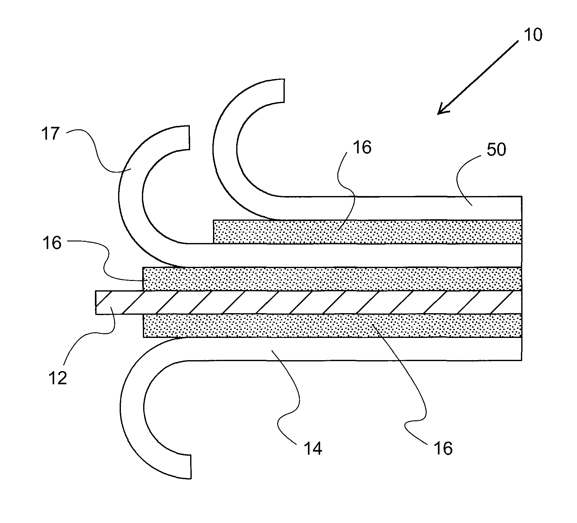
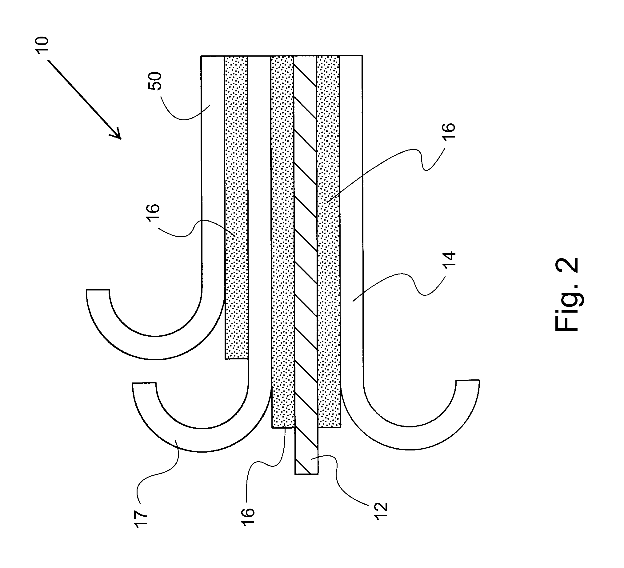
[0031]FIG. 2 shows an alternate embodiment of a combination through-wall masonry flashing and drainage device 10 that includes a flashing membrane 12, a first reinforcing cloth 14 affixed to a first side of flashing membrane 12 with an adhesive 16. A second reinforcing cloth 17 is affixed to a second side of flashing membrane 12 with adhesive 16. A wicking cloth 50 is affixed to second reinforcing cloth 17 with adhesive 16. For the purpose of clarity ...


PUM

PropertyMeasurementUnit
thicknessaaaaaaaaaa
thicknessaaaaaaaaaa
thicknessaaaaaaaaaa

Abstract

A combination through-wall masonry flashing and drainage device has a flashing membrane made of stainless steel sheet and a reinforcing cloth affixed to a first side of the flashing membrane. The flashing membrane has a thickness between 0.001 and 0.007 inch. When installed between an inner wall and an outer wall, water between the inner wall and outer wall is diverted to the outside of the outer wall by the through-wall masonry flashing and drainage device.

Description

[0001]This application is a continuation-in-part of U.S. non-provisional application Ser. No. 13 / 022,492, filed on Feb. 7, 2011 (to issue as U.S. Pat. No. 8,201,361 on Jun. 19, 2012), which is a continuation of U.S. application Ser. No. 10 / 710,845, filed Aug. 6, 2004 (now U.S. Pat. No. 7,900,404).BACKGROUND[0002]1. Field of the Invention[0003]The present invention is related generally to multi-layer flashing devices for masonry construction. More specifically, the present invention is related to a through-wall masonry flashing and drainage device.[0004]2. Description of the Related Art[0005]A masonry cavity wall traditionally is constructed having an inner back-up wall made of concrete, masonry block, brick, wood or steel frame construction, and an outer veneer wall of brick, stone, block, stucco, or other masonry. The two walls are separated by an air space or cavity. The width of this cavity can be specified by building code or architectural design preference. The design of two wa...

Claims


Application Information

Patent Timeline
Patent Type & Authority Patents(United States)
IPC IPC(8): B32B21/06E04B1/66B32B7/12E04D3/38B32B5/26B32B15/18B32B5/02B32B15/10E04B1/64E04B1/70
CPCE04B1/7046B32B7/12B32B5/26B32B21/06E04B1/665B32B5/024E04B1/644B32B5/028B32B2262/0253B32B15/18B32B2262/101B32B15/10B32B2419/00
Inventor WETMORE, CRAIG
Owner YORK MFG
Learn More