Circuit arrangement

a circuit arrangement and circuit technology, applied in the direction of electric controllers, motor/generator/converter stoppers, dynamo-electric converter control, etc., can solve the problem of inability to remove power loss in such cases, and achieve the effect of increasing the accuracy of holding voltag

Active Publication Date: 2014-11-18
SIEMENS AG
View PDF11 Cites 1 Cited by
  • Summary
  • Abstract
  • Description
  • Claims
  • Application Information

AI Technical Summary

Benefits of technology

[0014]Thus in clocked or pulse mode the suppressor diode is bypassed, through which the power loss arising can be advantageously reduced. At the same time, when the brake is deactivated, rapid demagnetization is still possible by the suppressor diode.
[0027]This makes it possible to increase the accuracy of the holding voltage or the holding current respectively of the holding brake in free-wheeling operation or these characteristic values can be adhered to more precisely. Thus the tolerances of the supply voltage, different on / off times, the temperature dependency of the brake winding resistance etc. can also be compensated for in order to get as close as possible to the lower value of the characteristic variables.

Problems solved by technology

If the holding brake is controlled with a pulse width-modulated voltage signal the problem arises here of the suppressor diode having free-wheeling current permanently applied to it, wherein the power loss arising in such cases cannot be removed.

Method used


Image

  • Circuit arrangement
  • Circuit arrangement
  • Circuit arrangement

Examples


Embodiment Construction

[0032]Throughout all the figures, same or corresponding elements may generally be indicated by same reference numerals. These depicted embodiments are to be understood as illustrative of the invention and not as limiting in any way. It should also be understood that the figures are not necessarily to scale and that the embodiments are sometimes illustrated by graphic symbols, phantom lines, diagrammatic representations and fragmentary views. In certain instances, details which are not necessary for an understanding of the present invention or which render other details difficult to perceive may have been omitted.

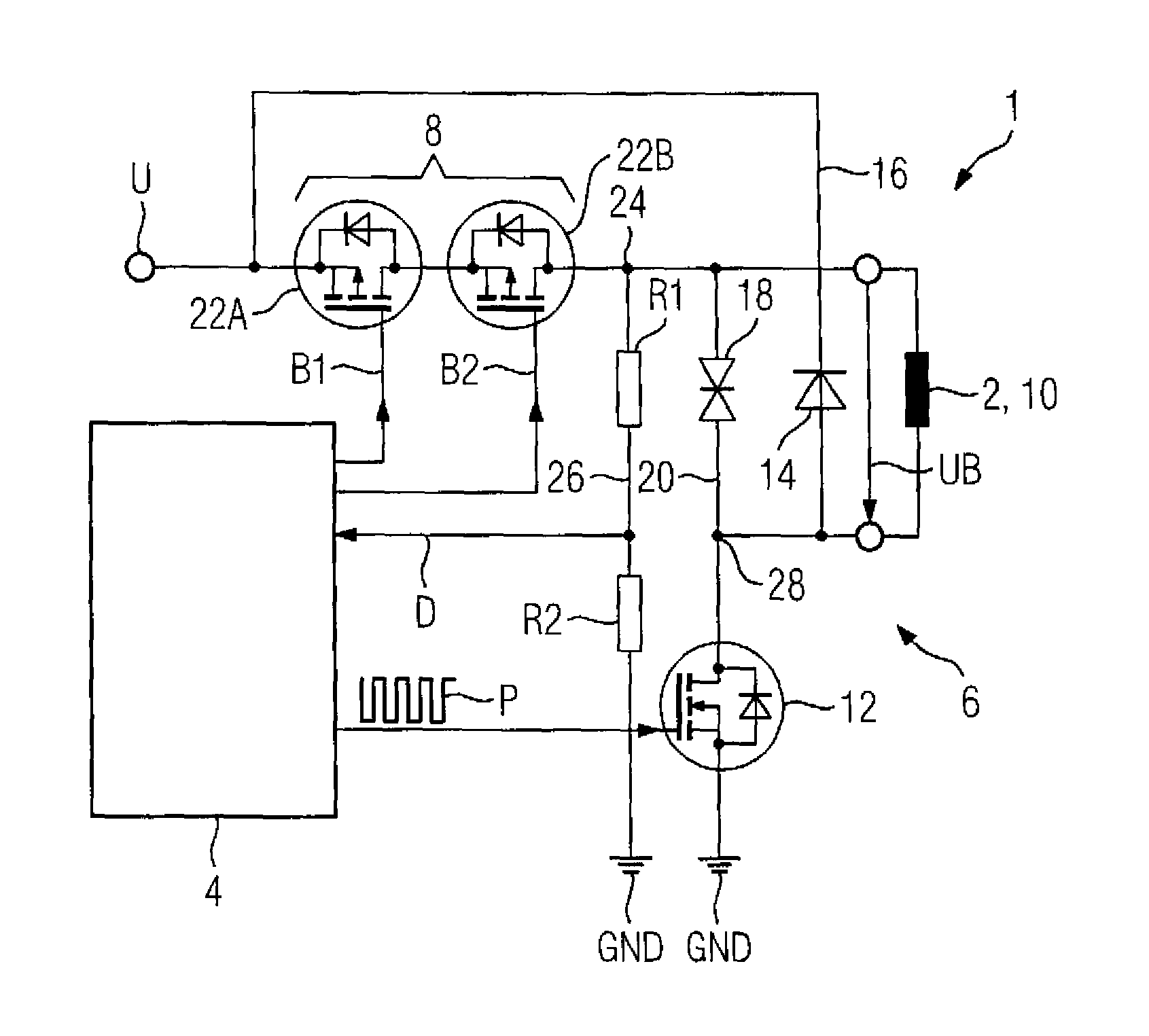
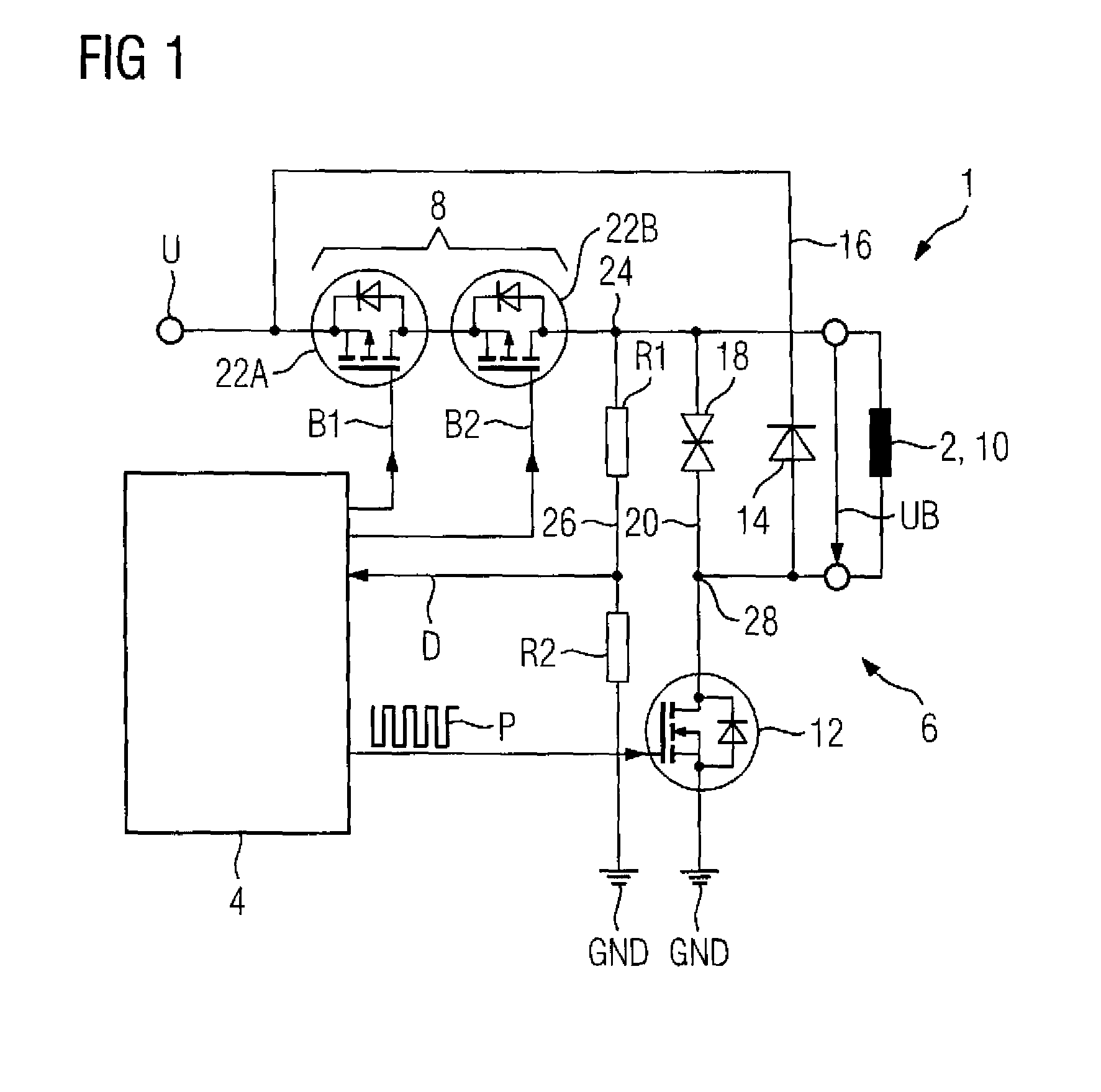
[0033]Turning now to the drawing, and in particular to FIG. 1, there is shown a principal circuit diagram of a first embodiment of a circuit arrangement in accordance with the present invention, generally designated by reference numeral 1, for a pulse width-modulated control of an electromagnetic holding brake 2. The circuit arrangement 1 is designed to be connected to a DC ...


PUM


Abstract

A circuit arrangement, especially for supplying an electromagnetic holding brake with a clocked supply voltage, includes a module for controlled provision of a clocked supply voltage for free-wheeling operation of the holding brake. The module has a switching unit for switching off the supply voltage for braking operation. A free-wheeling diode and a suppressor diode are connected in parallel to an inductance of the holding brake, with the free-wheeling diode being effective in free-wheeling operation only and the suppressor diode being effective in braking operation only.

Description

CROSS-REFERENCES TO RELATED APPLICATIONS[0001]This application claims the priority of European Patent Application, Serial No. 11159196, filed Mar. 22, 2011, pursuant to 35 U.S.C. 119(a)-(d), the content of which is incorporated herein by reference in its entirety as if fully set forth herein.BACKGROUND OF THE INVENTION[0002]The present invention relates to a circuit arrangement, especially for supplying power to an electromagnetic holding brake with a clocked supply voltage.[0003]The following discussion of related art is provided to assist the reader in understanding the advantages of the invention, and is not to be construed as an admission that this related art is prior art to this invention.[0004]One of the items disposed on a powerful electric motor, as is used for example as a variable-speed drive of an industrial machine, is an electromechanical holding brake. The brake serves to brake or to stop the motor shaft quickly and safely in a safety-critical situation (system error,...

Claims


Application Information

Patent Timeline
Patent Type & Authority Patents(United States)
IPC IPC(8): H02P3/00H02K7/10H02K23/68H02K27/30H02K49/00H02P3/04H02K17/32
CPCH02P3/04H02K49/00
Inventor HILD, BERNHARDMAUL, CHRISTIANSCHWESIG, GUNTERWALDERS, HANNO
Owner SIEMENS AG
Why Eureka
Try Eureka