
Methods and apparatus for converting waste materials into fuels and other useful products

a technology of waste materials and fuels, applied in the directions of transportation and packaging, separation processes, filtration separation, etc., can solve the problems of poor energy efficiency, little control, if any, over the composition of products, and energy-intensive processes

Active Publication Date: 2014-11-04
SYNPET TEKNOLOJI GELISTIRME
View PDF118 Cites 20 Cited by
  • Summary
  • Abstract
  • Description
  • Claims
  • Application Information

AI Technical Summary

Benefits of technology

This approach achieves high energy efficiency and produces products with low impurities, enabling the direct use of fuels and chemicals while reducing waste disposal costs and environmental impact, offering a sustainable and economically viable solution for managing diverse waste streams.

Problems solved by technology

A pyrolyzer typically heats organic materials at high temperatures, about 400-500° C., with poor energy efficiency and little, if any, control over the product composition.
As with incineration, pyrolysis aims to boil off the water using a very energy intensive process.
The typically large holding vessels used in pyrolysis results in significant interior temperature gradients, non-uniform waste treatment, and yields contaminated end products.
Gasification achieves a partial combustion of waste materials but, like pyrolysis, does not operate efficiently with wet waste as energy is expended to remove water from the feedstock.
There is little control over the type or composition of products due to non-uniform treatment of the feedstock and the principal usable energy-containing products are gases that are not as useful as other products.
Both the products of pyrolysis and gasification methods, respectively, can contain unacceptably high levels of impurities, e.g. tar, asphalt, and have low calorie content.
Typically, chlorinated hydrocarbons at levels of 1-2 ppm can be tolerated in hydrocarbons, but neither gasification nor pyrolysis methods can achieve such low levels with any reliability.
Poor heat transfer, nonuniform treatment, and an energy intensive water removal process have generally limited pyrolysis methods and gasification approaches to only about 30% energy efficiency.

Method used


Image

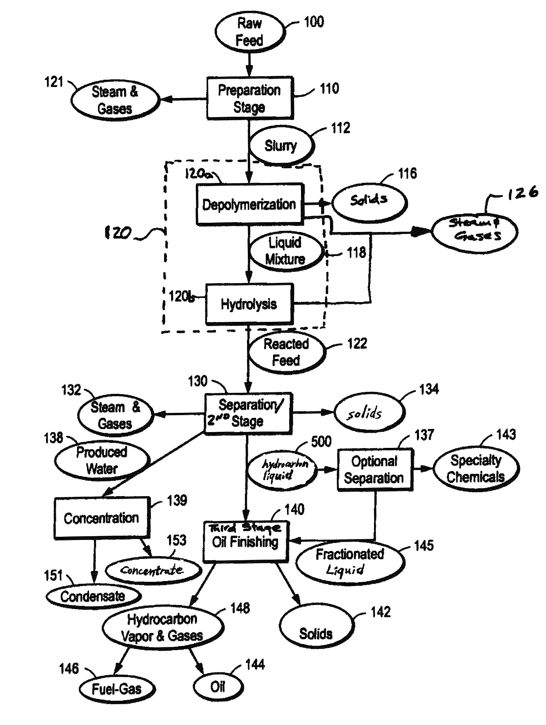
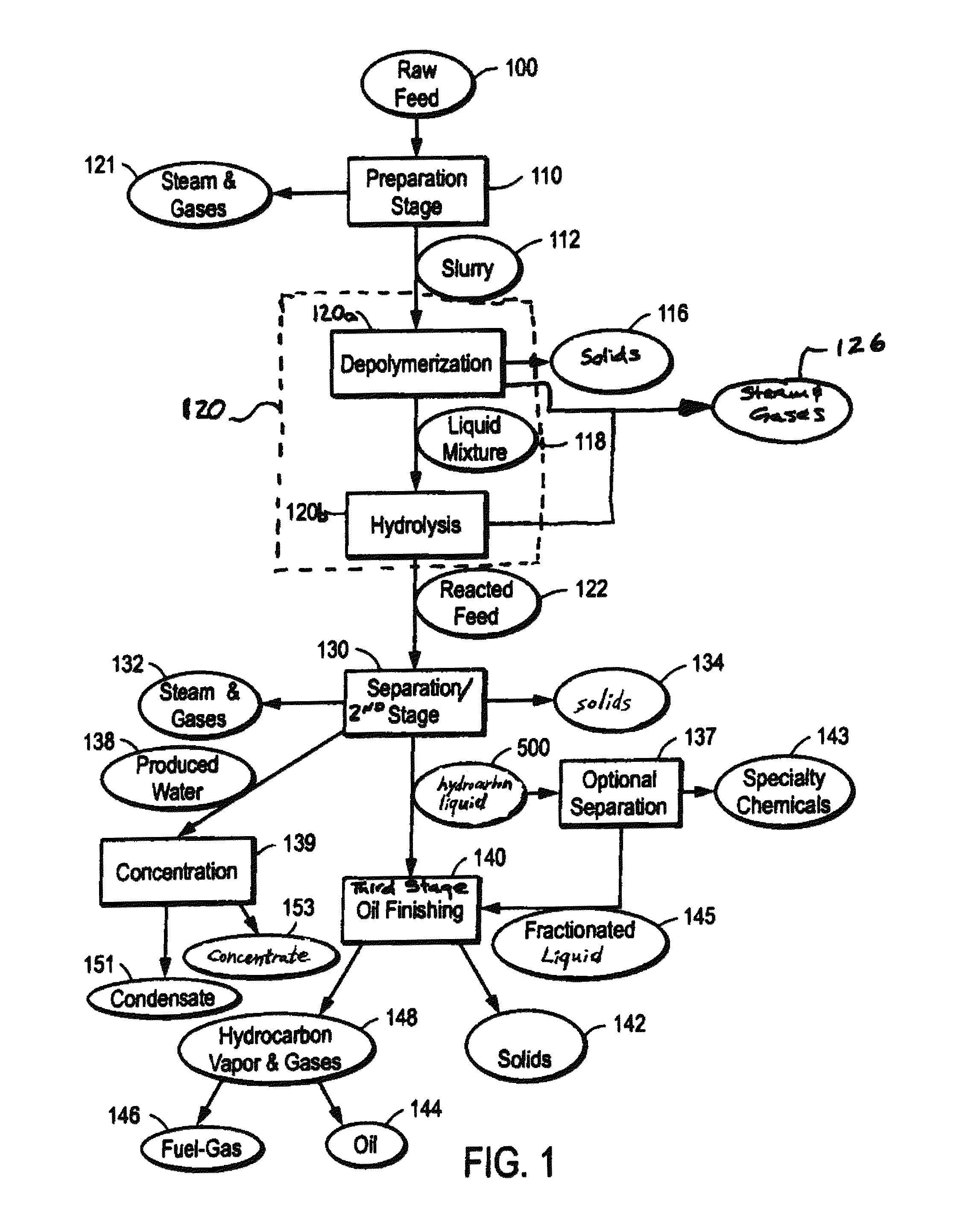
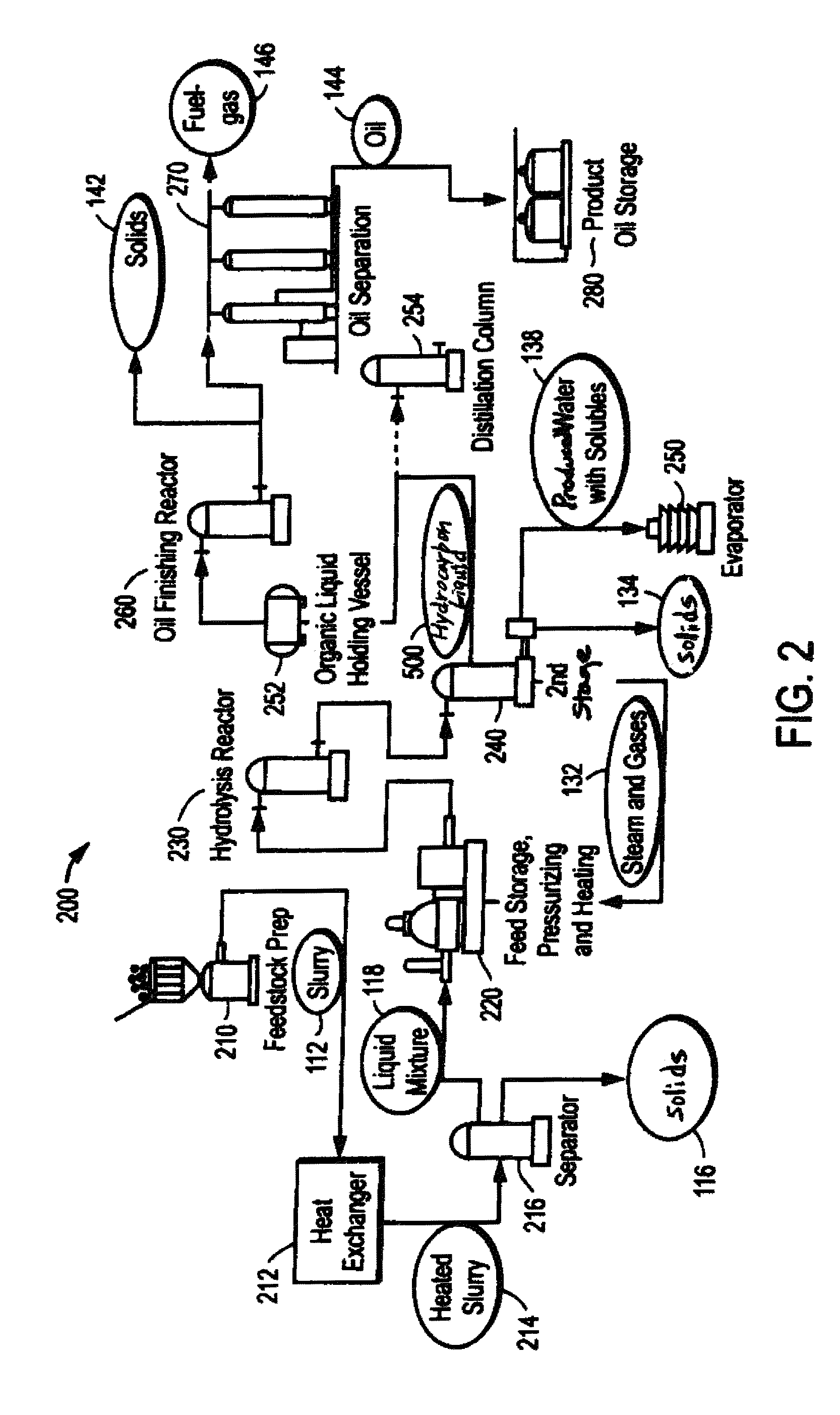
  • Methods and apparatus for converting waste materials into fuels and other useful products
  • Methods and apparatus for converting waste materials into fuels and other useful products
  • Methods and apparatus for converting waste materials into fuels and other useful products

Examples


example 1

Operating PlantAgricultural Waste

[0161]A full-sized, commercial-scale installation has been constructed with a system as illustrated in FIGS. 6 and 7 for processing of turkey offal and other animal-based agricultural waste. At peak capacity, the plant is designed to yield over 500 barrels of oil per day, based on an average raw feed input of approximately 250 tons. Approximately 40 to 50 barrels of oil per day may be returned to the system to generate heat for powering the system. The oil produced is a high-quality oil of a similar environmental grade as a #2 heating oil. The plant produces about 28,000 gallons of water per day from the feedstock itself. The plant also discharges cooling tower blowdown, boiler blowdown, domestic wastewater, scrubber blowdown and other non-contact cooling water, which is clean enough to discharge into a municipal sewage system and which is free of pathological vectors. The plant also produces about 20 tons of minerals and about 30 tons of concentrat...

example 2

Pilot Plant—Shredder Residue Processing

[0183]A pilot plant also has been built employing apparatus and processes of the present invention. As shown in FIG. 8, raw feed (typically SR, but the illustrated process also generally applies to MSW, which can be similar in composition, and other mixed plastic / rubber feeds) is received from the source, such a recycler, already ground in suitable size particles for processing (generally about ½″ to about 6″ across). Therefore very little feedstock preparation is generally required. It may be desirable to mix the raw feed with a liquid input 2003 to facilitate flowability of the raw feed and assist in reactions and heat transfer during subsequent processing. Persons of ordinary skill in the art may select suitable liquid inputs 2003 based on specific composition of particular raw feeds. For example, for SR as described herein, suitable liquid inputs include high molecular weight waste or virgin liquids such as used automotive fluids, crude oil...

example 2a

Thermal Cracking And Distillation of SR Hydrolyzed Oil

[0205]Approximately 10 liters of hydrocarbon liquid from the SR Example above was thermally cracked in a bench-scale reactor at temperatures near approximately 500° C. (930° F.) in six runs to produce a refined hydrocarbon oil, a fuel-gas, and a solid carbon product. A photo-graph of the bench-scale thermal cracking unit is shown in FIG. 10. Gas and oil vapor were vented during the reaction in order to maintain a target pressure. The run was terminated when gas evolution stopped, as indicated by a constant gas pressure. The distribution of oils / gas / carbon fractions from the thermal cracker was about 84%, 10%, and 6%, respectively.

[0206]One cracked oil product is a renewable diesel similar to conventional diesel fuel. This cracked oil can be used for a variety of purposes, e.g. as a direct replacement for diesel fuel or as a blending component for diesel fuel. The chemical and physical characteristics of the cracked oil are listed...


PUM

PropertyMeasurementUnit
pressuresaaaaaaaaaa
temperaturesaaaaaaaaaa
pressuresaaaaaaaaaa

Abstract

Conversion of waste and other organic feedstock into sustainable energy, feed, fertilizer, and other useful products of reliable purities is accomplished using water, heat, and pressure. More specifically, the invention provides methods and apparatus that handle mixed streams of various feedstocks, e.g. agricultural waste, biological waste, municipal solid waste, municipal sewage sludge, and shredder residue, to yield gas, oil, specialty chemicals, and carbon solids that can be used as is or are further processed. Useful products can be diverted at various points of the process or internalized to enhance the efficiency of the system.

Description

CROSS-REFERENCES TO RELATED APPLICATIONS[0001]The present application is a continuation-in-part of U.S. patent application Ser. No. 10 / 717,076, filed Nov. 18, 2003 and published as U.S. 2004-0192980, now U.S. Pat. No. 8,003,833 which claims the benefit of priority under 35 U.S.C. §119(e) to U.S. Provisional Application No. 60 / 458,520, filed Mar. 28, 2003, the contents of which are incorporated herein by reference in their entirety. The present application is also a continuation-in-part of U.S. patent application Ser. No. 11 / 529,825, filed Sep. 29, 2006 and published on May 3, 2007 as U.S. 2007-0098625, now U.S. Pat. No. 7,771,699 which claims the benefit of priority under 35 U.S.C. §119(e) to U.S. Provisional Application Nos. 60 / 721,836, 60 / 727,491, filed Oct. 17, 2005, 60 / 778,034, filed Feb. 28, 2006, 60 / 812,275, filed Jun. 9, 2006, and 60 / 840,207, filed Aug. 25, 2006, the contents of which are incorporated herein by reference in their entirety. The present application is a further...

Claims


Application Information

Patent Timeline
Patent Type & Authority Patents(United States)
IPC IPC(8): C07C1/20
CPCC10G1/002C10G2300/205C10G2300/1018C10G2300/1003C10G2300/1014C10G2300/805Y02W10/33Y02W10/37Y02P30/20B09B3/00B09B3/40C07C1/02C10G3/00C10L1/04
Inventor APPEL, BRIAN S.ADAMS, TERRY N.FREISS, JAMES H.EINFELDT, CRAIG T.LANGE, WILLIAM F.JONES, SHANNON M.
Owner SYNPET TEKNOLOJI GELISTIRME
Learn More