
Pipe/filler unit, internal heat exchanging type distillation column and production method thereof

a technology of distillation column and pipe/filler unit, which is applied in the direction of lighting and heating apparatus, separation processes, applications, etc., can solve the problems of inability to replace or the like of filler, inability to recover sufficient performance, and in particular the distillation section, so as to facilitate maintenance and improve the close contact feature

Active Publication Date: 2014-10-28
KIMURA CHEM PLANTS CO LTD +1
View PDF12 Cites 0 Cited by
  • Summary
  • Abstract
  • Description
  • Claims
  • Application Information

AI Technical Summary

Benefits of technology

Enables easy maintenance and cleaning of the distillation section, improves heat transfer efficiency, and reduces operational complexity by allowing the pipe / filler unit to be used as a constructional member for internal heat exchanging type distillation columns, enhancing both distillation performance and energy-saving properties.

Problems solved by technology

In this case, even when sufficient cleaning cannot be necessarily performed, there is a problem in that replacement or the like of filler cannot be performed, and sufficient performance cannot be recovered.
However, as described above, in the present circumstances, it is a situation in which the distillation section, especially, the filler of the stripping section is not easily extracted.Patent Document 1: Unexamined Japanese Patent Application, First Publication No. 2004-016929Patent Document 2: Unexamined Japanese Patent Application, First Publication No. 2004-037017

Method used


Image

  • Pipe/filler unit, internal heat exchanging type distillation column and production method thereof
  • Pipe/filler unit, internal heat exchanging type distillation column and production method thereof
  • Pipe/filler unit, internal heat exchanging type distillation column and production method thereof

Examples


embodiment 1

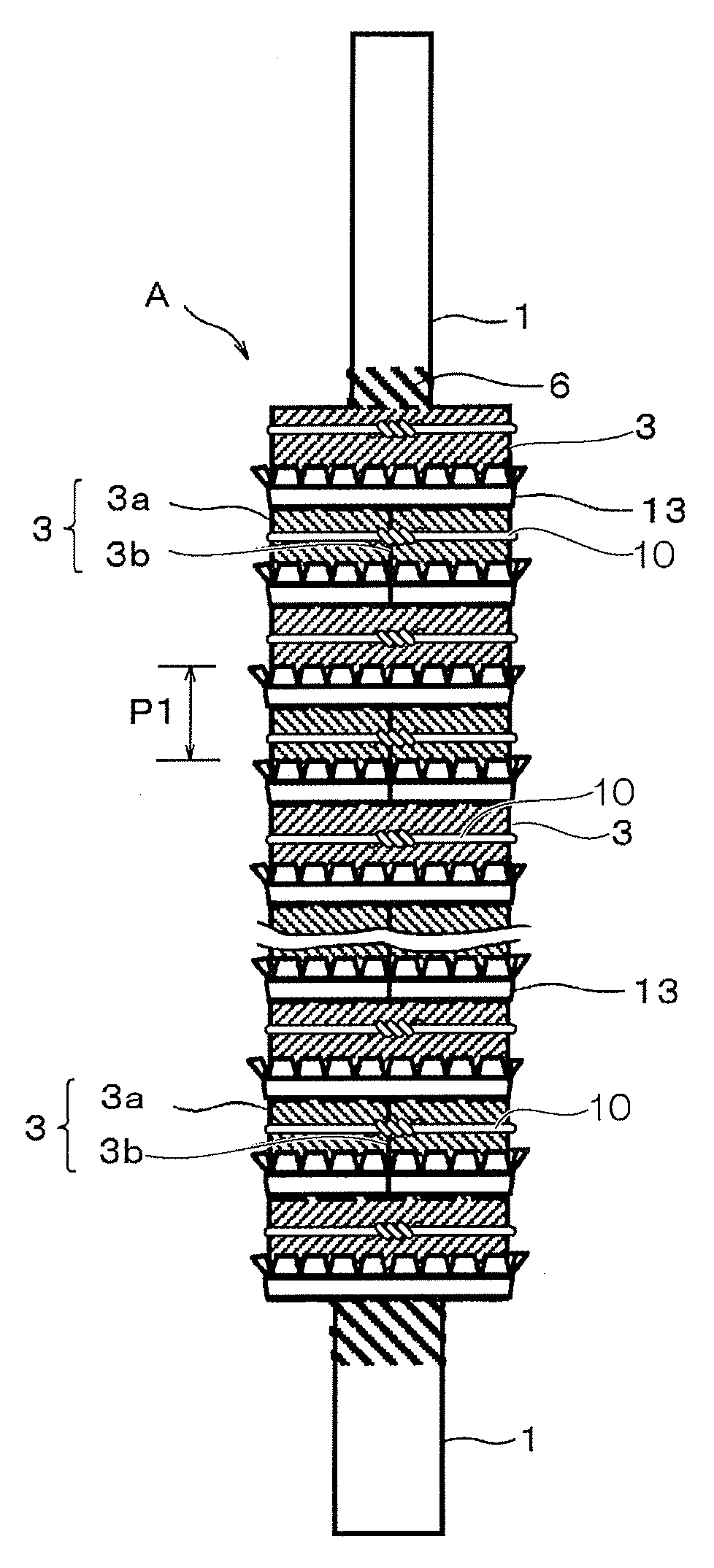
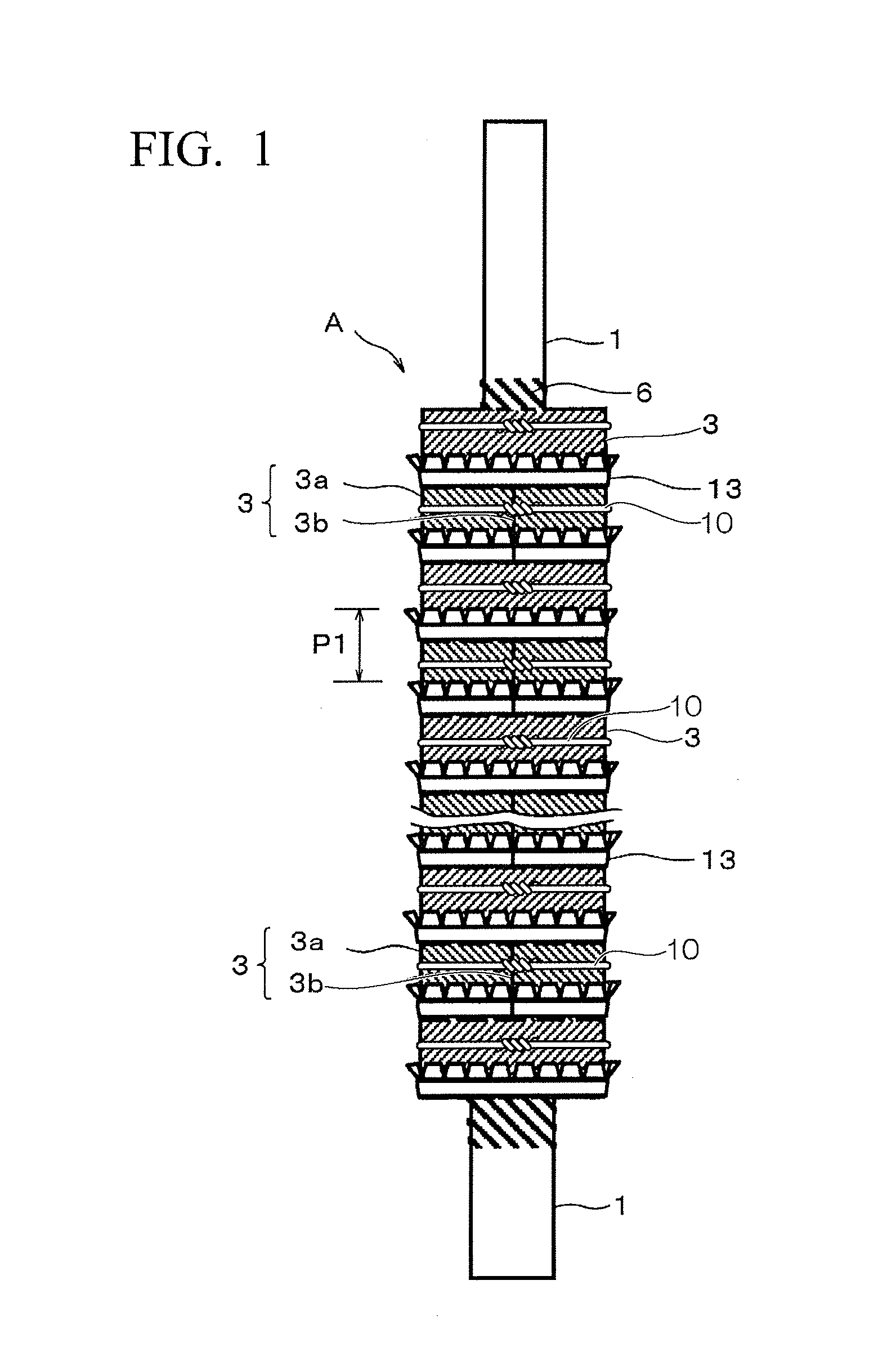
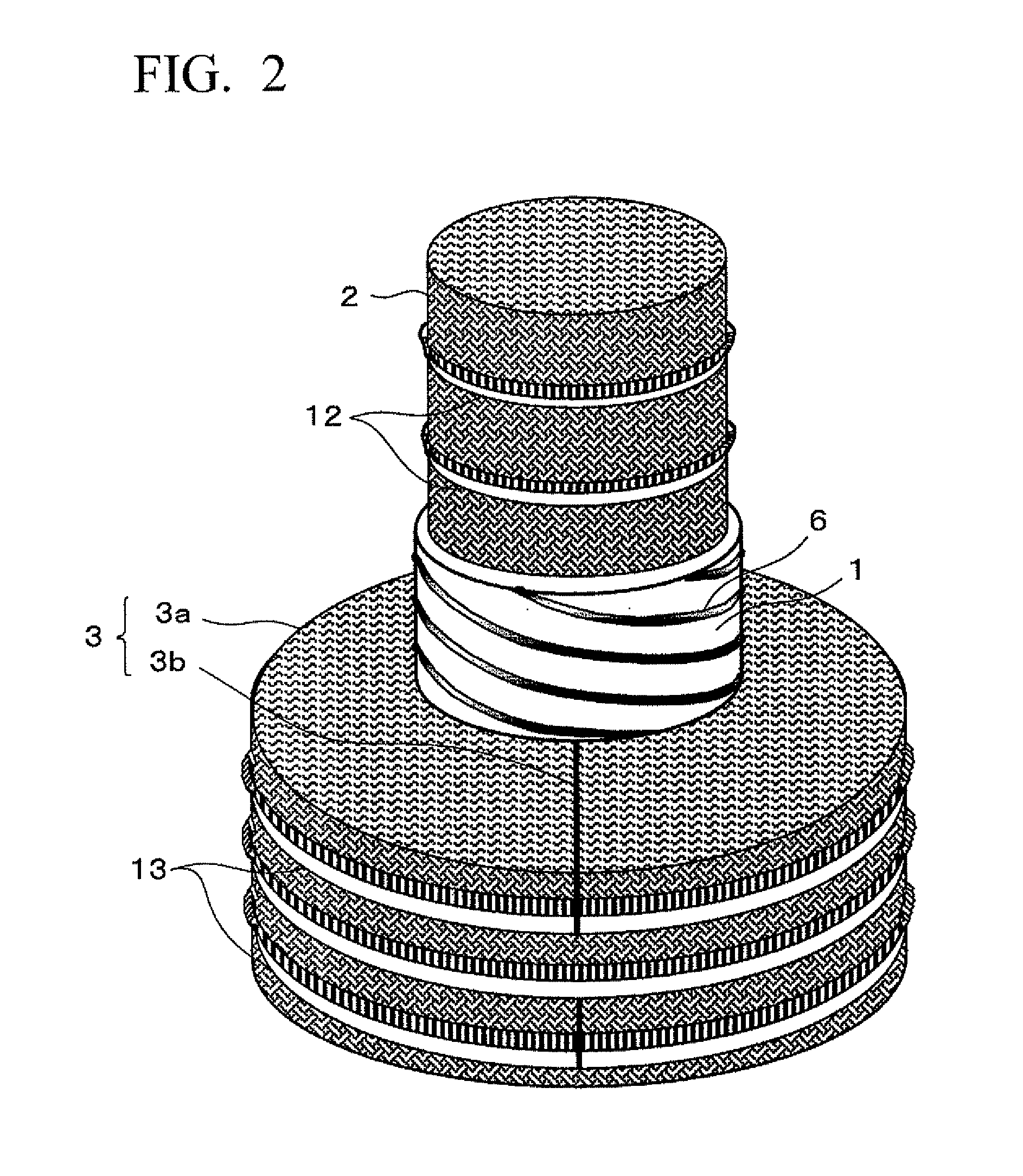
[0121]FIG. 1 is a view showing the configuration of a pipe / filler unit according to one embodiment (Embodiment 1) of the present invention, FIG. 2 is a perspective view showing the configuration of main parts, FIGS. 3A to 3C are views showing the configuration of an outside regular filler layer of the present invention, and FIG. 3A is a perspective view, FIG. 3B is a plan view, and FIG. 3C is a side view, and FIG. 4 is a front sectional view of the pipe / filler unit of the present invention.

[0122]A pipe / filler unit A of this Embodiment 1 includes a pipe 1 where heat is exchanged between the inside and the outside of a pipe wall, an inside regular filler layer 2 disposed inside the pipe 1 so as to abut an inner peripheral surface of the pipe 1, and an outside regular filler layer 3 disposed outside the pipe 1 so as to surround the pipe 1 and closely contact an outer peripheral surface of the pipe 1.

[0123]In addition, the diameter of the pipe 1 is adjusted on the way in a height direct...

embodiment 2

[0138]FIG. 6 is a view showing the configuration of an internal heat exchanging type distillation column H according to Embodiment 2 of the present invention using the pipe / filler unit of the above Embodiment 1 as a constituent material of a distillation section, and FIG. 7 is a sectional view taken along a line X-X of FIG. 6.

[0139]Additionally, FIG. 8 is a sectional view showing the configuration of an internal heat exchanging type distillation column lower body Ha before the pipe / filler unit, etc. of the present invention are disposed.

[0140]The internal heat exchanging type distillation column H of this Embodiment 2, as shown in FIGS. 6 and 7, includes a body barrel 21, a plurality of pipes 1 that is inserted into the body barrel 21, and an upper pipe plate 23a and a lower pipe plate 23b that connect the plurality of pipes 75 to the body barrel 51. In addition, a pipe inside 24 and a pipe outside 25 of each pipe 1 are separated from each other, the pipe inside 24 functions as an e...


PUM

PropertyMeasurementUnit
diameteraaaaaaaaaa
angleaaaaaaaaaa
thicknessaaaaaaaaaa

Abstract

An inside regular filler layer is disposed inside a pipe where heat is exchanged between an inside and an outside of a pipe wall so as to abut an inner peripheral surface of the pipe, and an outside regular filler layer is disposed outside the pipe so as to surround the pipe and closely contact an outer peripheral surface of the pipe. The outer peripheral surface of the pipe is subjected to close contact-promoting processing in order to enhance close contacting feature between the outer peripheral surface and the outside regular filler layer. The pipe / filler unit is used for the distillation section of an internal heat exchanging type distillation column.

Description

CROSS REFERENCE TO RELATED APPLICATIONS[0001]This application is a national stage of International Patent Application No. PCT / JP2007 / 053756, filed Feb. 28, 2007, and claims the benefit of priority under 35 U.S.C. §119 of Japanese Patent Application No. 2006-208815, filed Jul. 31, 2006, the entire contents of which are incorporated herein by reference.TECHNICAL FIELD[0002]The present invention relates to a pipe / filler unit that has a structure formed by combining a pipe with a regular filler, an internal heat exchanging type distillation column of a packed column type which is produced using the pipe / filler unit, for example, which is adapted such that a pipe inside and a pipe outside of a single pipe or each pipe are isolated from each other inside the body barrel by connecting the single pipe or a plurality of pipes with a body barrel by both end pipe plates, a difference is caused in operating temperature by causing a difference in operation pressure between the pipe inside and th...

Claims


Application Information

Patent Timeline
Patent Type & Authority Patents(United States)
IPC IPC(8): B01D3/28F28F13/00F28D3/02B21D53/02F28D7/16F28D5/02B01D3/32
CPCF28D7/16B01D3/28F28F13/003F28D3/02F28F2280/02Y10T29/49396Y10T29/49377
Inventor NAKANISHI, TOSHINARIASO, KAZUMASAIUCHI, KENSUKEHORIUCHI, KINPEINAKAIWA, MASARU
Owner KIMURA CHEM PLANTS CO LTD
Learn More