
Chemical mechanical polishing slurry composition and method for producing semiconductor device using the same

a technology of chemical mechanical polishing and slurry composition, which is applied in the direction of polishing compositions with abrasives, other chemical processes, chemistry apparatus and processes, etc., can solve the problems of particle contamination, long time required, and the rate of tantalum used as a barrier metal is not high, and achieves excellent stability over time and dispersion stability, excellent degree of planarization, and high polishing rate

Active Publication Date: 2014-09-23
SOULBRAIN CO LTD
View PDF7 Cites 9 Cited by
  • Summary
  • Abstract
  • Description
  • Claims
  • Application Information

AI Technical Summary

Benefits of technology

[0008]An object of the present invention is to provide a slurry composition for chemical mechanical polishing, which has a conspicuously high polishing rate for silicon oxide film, is capable of selectively preventing the removal of silicon nitride film, does not cause an imbalance in polishing, can give an excellent degree of planarization, has excellent stability over time and dispersion stability, causes less generation of particles and scratches due to the optimal composition of additives, and produces very satisfactory polished surfaces of barrier metals and oxides.

Problems solved by technology

However, in a basic zone, the removal rate of tantalum used as a barrier metal is not so high that a long time is required.
Furthermore, since large amounts of polishing materials are used in order to increase the polishing rate for oxide film, there are disadvantages such as particle contamination and high occurrence of scratches.
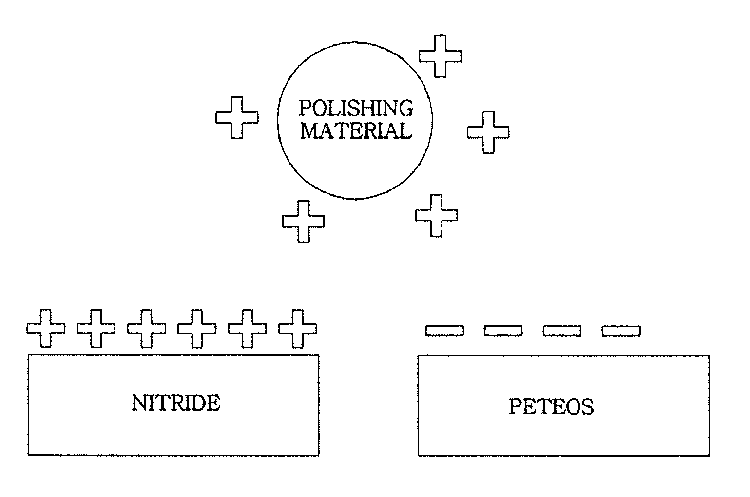
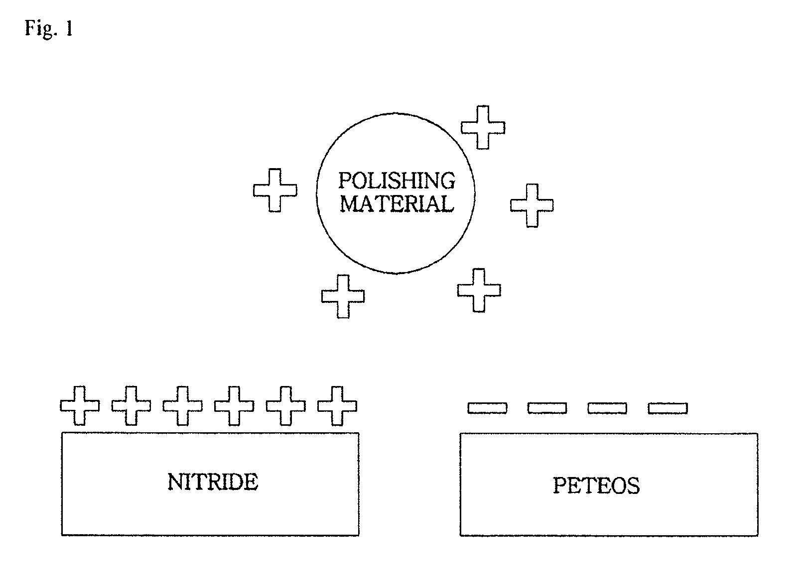
On the other hand, in an acidic zone, the particle contamination after polishing tends to occur at a lower level than in a basic zone; however, there is a disadvantage that an isoelectric point of the colloidal silica used as the polishing material is reached, and the dispersion stability of the slurry deteriorates.

Method used


Image

  • Chemical mechanical polishing slurry composition and method for producing semiconductor device using the same
  • Chemical mechanical polishing slurry composition and method for producing semiconductor device using the same
  • Chemical mechanical polishing slurry composition and method for producing semiconductor device using the same

Examples


experiment examples

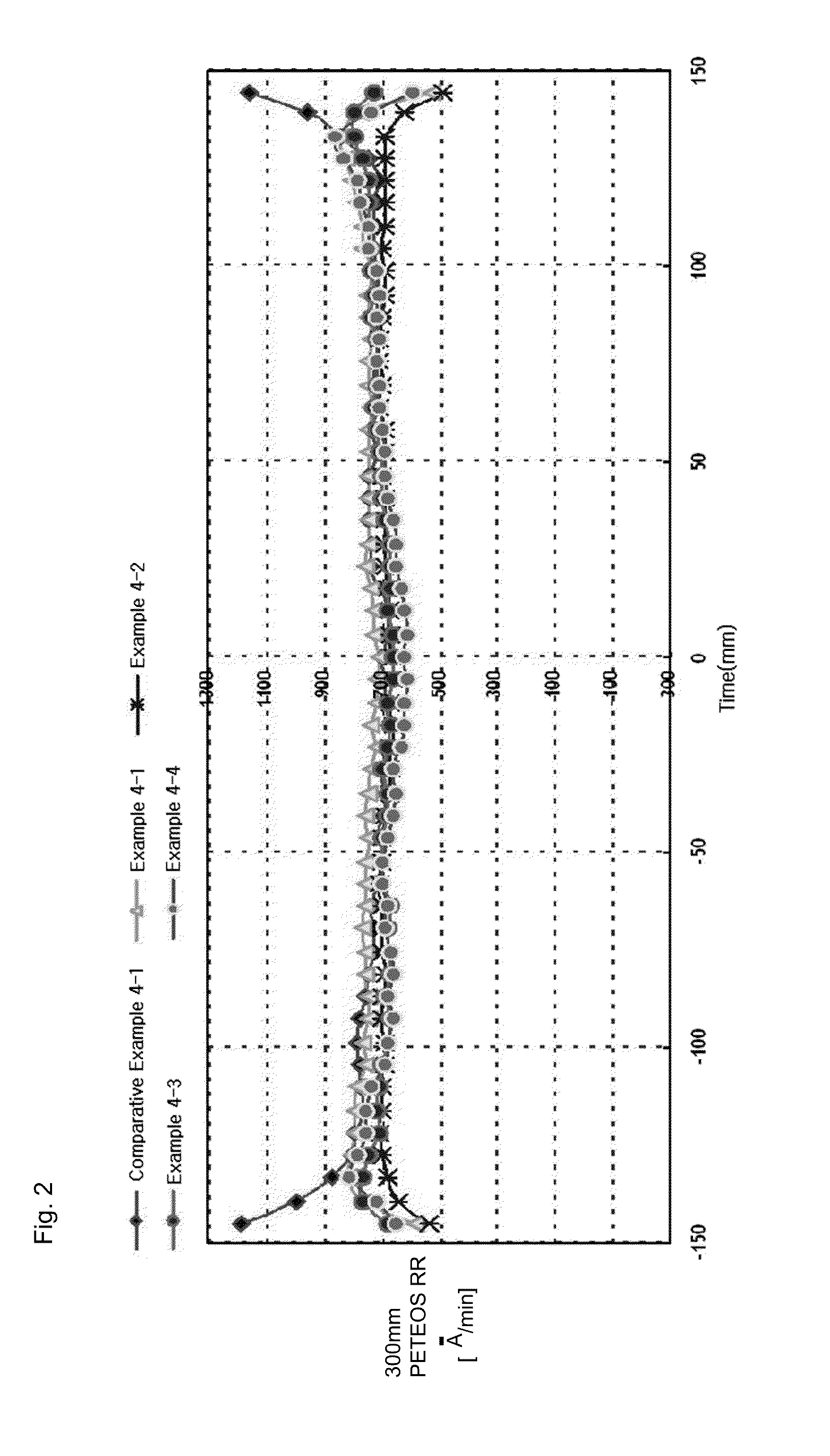
[0054]A tantalum specimen wafer on which a thin film having a thickness of 1000 Å is deposited was used for polishing. For a silicon oxide film, a specimen wafer on which a PETEOS thin film having a thickness of 10000 Å was used, and for a silicon nitride film, a specimen wafer on which a thin film having a thickness of 3000 Å was used.

[0055]As for the polishing apparatus, Poli 400 (manufactured by G & P Technology, Inc.) was used, and a polishing test was carried out using a polishing pad, IC1000 (Dow Corning Corp.). The polishing conditions were such that the table / head speed was 93 / 87 rpm, the polishing pressure was 140 g / cm2, the slurry supply flow rate was 200 ml / min, and the polishing time was 30 seconds to 60 seconds.

[0056]The tantalum thin film thickness was determined by measuring the surface resistance using a four-point probe surface resistance analyzer (AIT Semiconductor, Inc.), and then calculating the thickness therefrom. The thin film thicknesses of PETEOS and silicon...

experiment example 1

[0057]Polishing slurry compositions of Examples and Comparative Examples were prepared in the compositions as indicated in the following Table 1. Furthermore, an evaluation of polishing was carried out for the prepared polishing slurry compositions, and the results are also presented in Table 1.

[0058]The colloidal silicas used in the following Table 1 were colloidal silicas having an average particle size of 35 nm, 55 nm and 75 nm, respectively, and each of the colloidal silicas was used after uniformly surface treating the colloidal silica with γ-aminopropyltriethoxysilane in an amount of 0.25% by weight relative to the total amount of the polishing agent.

[0059]Furthermore, a polishing slurry was prepared in a composition including 5% by weight of a polishing material, 0.1% by weight of 5-aminotetrazole as a corrosion inhibitor, and 1.0% by weight of hydrogen peroxide as an oxidizing agent. During the preparation of the slurry, the slurry was adjusted to a desired pH value using ni...

experiment example 2

[0062]An evaluation of polishing was carried out by changing the pH value of the compositions of Example 1-2. The results are presented in the following Table 2.

[0063]

TABLE 2Content ofPETEOSSiNPETEOSExperimentpolishingRRRRRR / SiNExamplepHColloidal silicamaterial (wt %)(Å / min)(Å / min)RRExample 2-13.0055 nm,512222405.09silane-treatedExample 2-23.4055 nm,513592475.50silane-treatedExample 2-23.9055 nm,512943004.31silane-treatedComparative2.0055 nm,52214080.54Example 2-1silane-treatedComparative5.0055 nm,5———Example 2-2silane-treated

[0064]As can be seen from Table 2, the polishing rate for PETEOS reached the maximum at pH 3.4, and the polishing rate for a silicon nitride film tended to increase as the pH increased. At pH 5, aggregation of the polishing material occurred.


PUM

PropertyMeasurementUnit
particle sizeaaaaaaaaaa

Abstract

A slurry composition for chemical mechanical polishing, including 0.1% to 20% by weight of an aminosilane-surface treated polishing agent; 0.001% to 5% by weight of an additive selected from amino acids, amino acid derivatives, salts thereof, and combinations thereof; 0.0001% to 0.5% by weight of a corrosion inhibitor; and 0.01% to 5% by weight of an oxidizing agent, with the balance being a solvent, is provided. The slurry composition for chemical mechanical polishing has a conspicuously high polishing rate for silicon oxide films, is capable of selectively preventing the removal of silicon nitride films, does not cause an imbalance in polishing, gives an excellent degree of planarization, has excellent stability over time and dispersion stability, causes less generation of particles and scratches, and produces very satisfactory polished surfaces of barrier metal films and oxide films.

Description

BACKGROUND OF THE INVENTION[0001]1. Field of the Invention[0002]The present invention relates to a slurry composition for chemical mechanical polishing (CMP), and more particularly, the present invention relates to a slurry composition for chemical mechanical polishing, which exhibits high polishing rates for barrier metal films and silicon oxide films, is capable of controlling the polishing rate for silicon nitride films, and thereby has a high polishing selection ratio.[0003]2. Description of Related Art[0004]In the chemical mechanical polishing process, which is one of the production processes for semiconductor devices, a polishing process is carried out by mounting on a platen a wafer that is to be subjected to a planarization process, bringing the surface of this wafer into contact with a pad of a polishing machine, and then rotating a rotating plate and the pad of the polishing machine while a slurry is supplied. That is, a slurry flows between the wafer surface and the pad, ...

Claims


Application Information

Patent Timeline
Patent Type & Authority Patents(United States)
IPC IPC(8): H01L21/302C09G1/02C09K13/00H01L21/3105
CPCH01L21/31053C09G1/02C09K3/1436C09K3/1463
Inventor HAN, DEOK-SUKIM, HWAN-CHULKIM, SEOK-JOOPARK, HYU-BUM
Owner SOULBRAIN CO LTD
Learn More