Dental wedge and former device

Active Publication Date: 2014-09-16
ZEST IP HLDG
View PDF19 Cites 2 Cited by
  • Summary
  • Abstract
  • Description
  • Claims
  • Application Information

AI Technical Summary

Benefits of technology

The present invention provides a dental wedge and forming device that can prevent collapse or crushing of the dental matrix band and can be used in dental restorative procedures to seal the dental matrix band to the proximal surface of the tooth. The dental wedge device includes an elongated element or nose that is curved and includes a concave surface to seal the floor of the dental matrix band. The curved elongated element also helps to direct the side-by-side orientation of identical wedge devices and efficiently seals the dental matrix band to the proximal surface of the tooth. The dental wedge device can be used in combination with a dental separator or sectional ring to increase the wedging force against the matrix band. The dental wedge device is compatible with composite filling material used in dental restorations and avoids the formation of a dental restoration morphology that is grossly distorted in size and shape.

Problems solved by technology

Unfortunately, in the past, wedges and dental separator rings have caused the collapse of the matrix band and created gaps between the matrix band and the tooth being restored.
Collapse of the matrix band does not allow a proper formation or morphology of restorative material in the tooth.
Gaps in the matrix band also permit restorative material to flow outside the confines of the matrix band creating a “flash”, which is highly undesirable.
The latter problem is especially acute when composite material is used to create the dental restoration.

Method used


Image

  • Dental wedge and former device
  • Dental wedge and former device
  • Dental wedge and former device

Examples


Embodiment Construction

[0036]Various aspects of the present invention will evolve from the following detailed description of the preferred embodiments thereof which should be referenced to the prior described drawings.

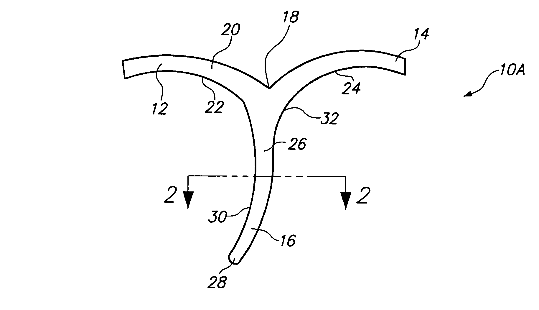
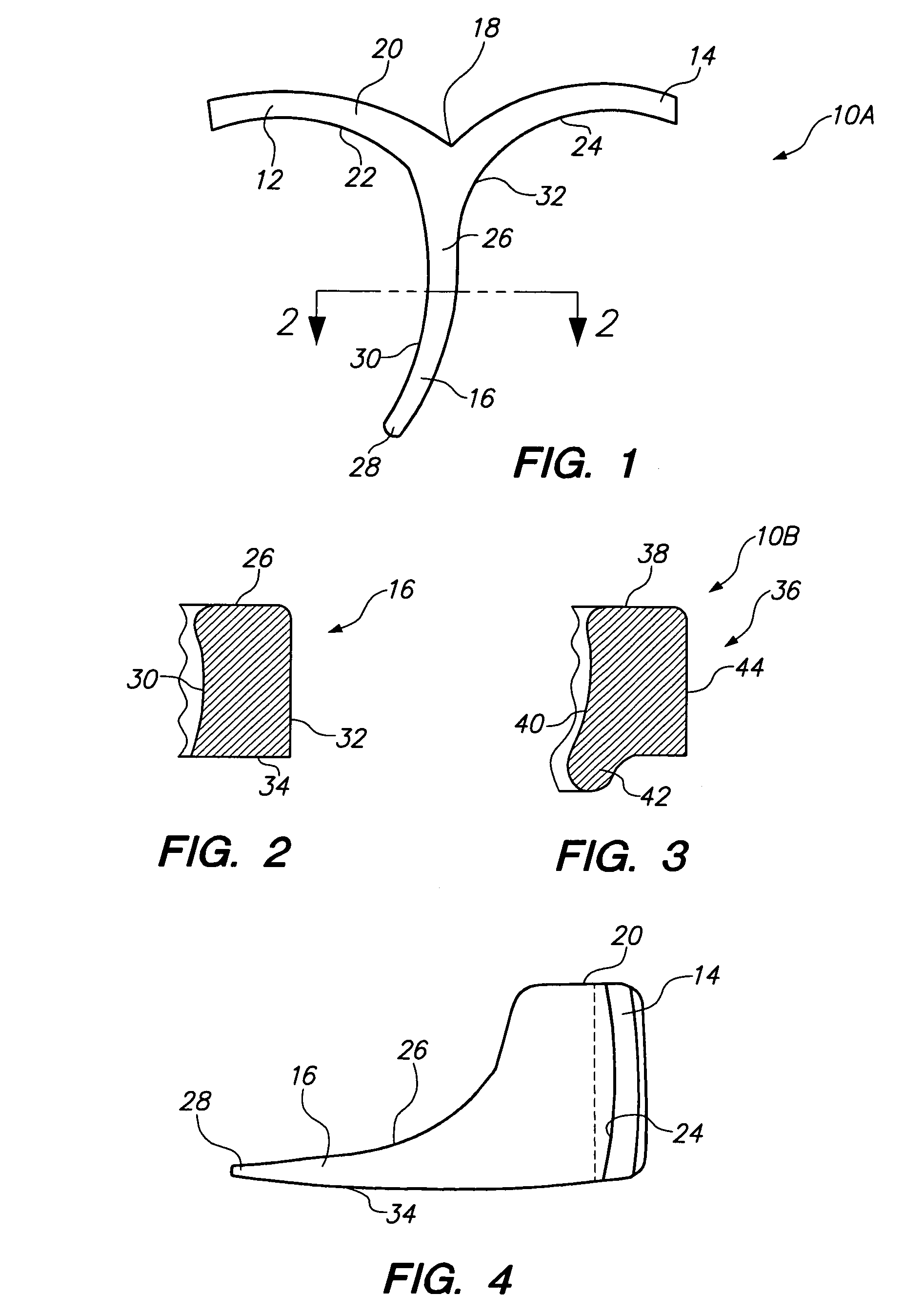
[0037]An embodiment of the invention is depicted by reference character 10, followed by an uppercase letter to denote variations thereof. With respect to FIG. 1, an embodiment of a dental wedge and former 10A is shown. Device 10A includes as one of its elements ears, wings, or flanges 12 and 14 which converge or “y” into a downwardly projecting elongated element or nose 16 when viewed from its side, FIG. 4. Wings 12 and 14 converge at a cusp or recess 18, the purpose in which will be discussed hereinafter. Also, wings 12 and 14 include an upper surface 20, above lower surface 34, defining the height of wings 12 and 14. Wings or flanges 12 and 14 possess curved or concave surfaces 22 and 24, respectively. Wedge 10A may be formed of polymeric material.

[0038]Nose or elongated member 16 of devic...


PUM


Abstract

A dental wedge and forming device utilizing a unitary body having a pair of wings which are intended to lie against the outer surfaces of adjacent teeth, either on the lingual or buccal region of the teeth. A curved nose is constructed to extend between the adjacent teeth and includes a flat side and an opposite radiused side. A pair of the devices are nested in opposition in order to hold a dental matrix band in place about a prepared tooth, thus allowing a dental practitioner to practice proper biomimetic restorative techniques.

Description

CROSS-REFERENCE TO RELATED APPLICATION[0001]The application claims the benefit, under 35 U.S.C. §119(e), of U.S. Provisional Patent Application No. 61 / 404,762 filed on 8 Oct. 2010, which is incorporated herein, by reference, in its entirety.BACKGROUND OF THE INVENTION[0002]The present invention relates to a novel and useful dental wedge and former device which is used in conjunction with dental restoration techniques.[0003]The treatment of interproximal cavities requires the dental practitioner to remove decayed enamel and dentin along the side or proximal wall of a tooth which is nested adjacent, and often contacts, healthy tooth. In general, a matrix band is placed around the tooth in order to confine the filling materials to the removed portion of the tooth which is to be filled. At this point, dental wedges are normally are used to spread adjacent teeth and to stabilize the matrix band. In addition, a dental separator ring may also be employed to apply pressure to further separa...

Claims


Application Information

Patent Timeline
IPC IPC(8): A61C7/00
CPCA61C7/00A61C5/127A61C5/88
Inventor GOTTLIEB, MARCBRUNS, CRAIG
Owner ZEST IP HLDG
Why Eureka
Try Eureka