
Control device of vehicle oil supply device

a technology of control device and oil supply device, which is applied in the direction of electric propulsion mounting, machine/engine, auxilary lubrication, etc., can solve the problems of deteriorating fuel efficiency and wasteful driving of electric oil pumps, and achieve the improvement of fuel efficiency, fuel efficiency, and wasteful operation of electric oil pumps.

Inactive Publication Date: 2014-09-16
TOYOTA JIDOSHA KK
View PDF21 Cites 10 Cited by
  • Summary
  • Abstract
  • Description
  • Claims
  • Application Information

AI Technical Summary

Benefits of technology

This approach shortens the overlap period of pump operation, reducing wasteful electric pump operation and improving fuel efficiency by ensuring the electric pump is stopped when its load increases, thus enhancing the vehicle's running distance per unit fuel consumption.

Problems solved by technology

For example, if an output oil pressure of the mechanical oil pump is equal to or greater than a steady-state output oil pressure of the electric oil pump, it is wasteful to continue driving the electric oil pump.
If the electric oil pump is driven more than necessary in this way, fuel efficiency may deteriorate, for example.

Method used


Image

  • Control device of vehicle oil supply device
  • Control device of vehicle oil supply device
  • Control device of vehicle oil supply device

Examples


embodiment 1

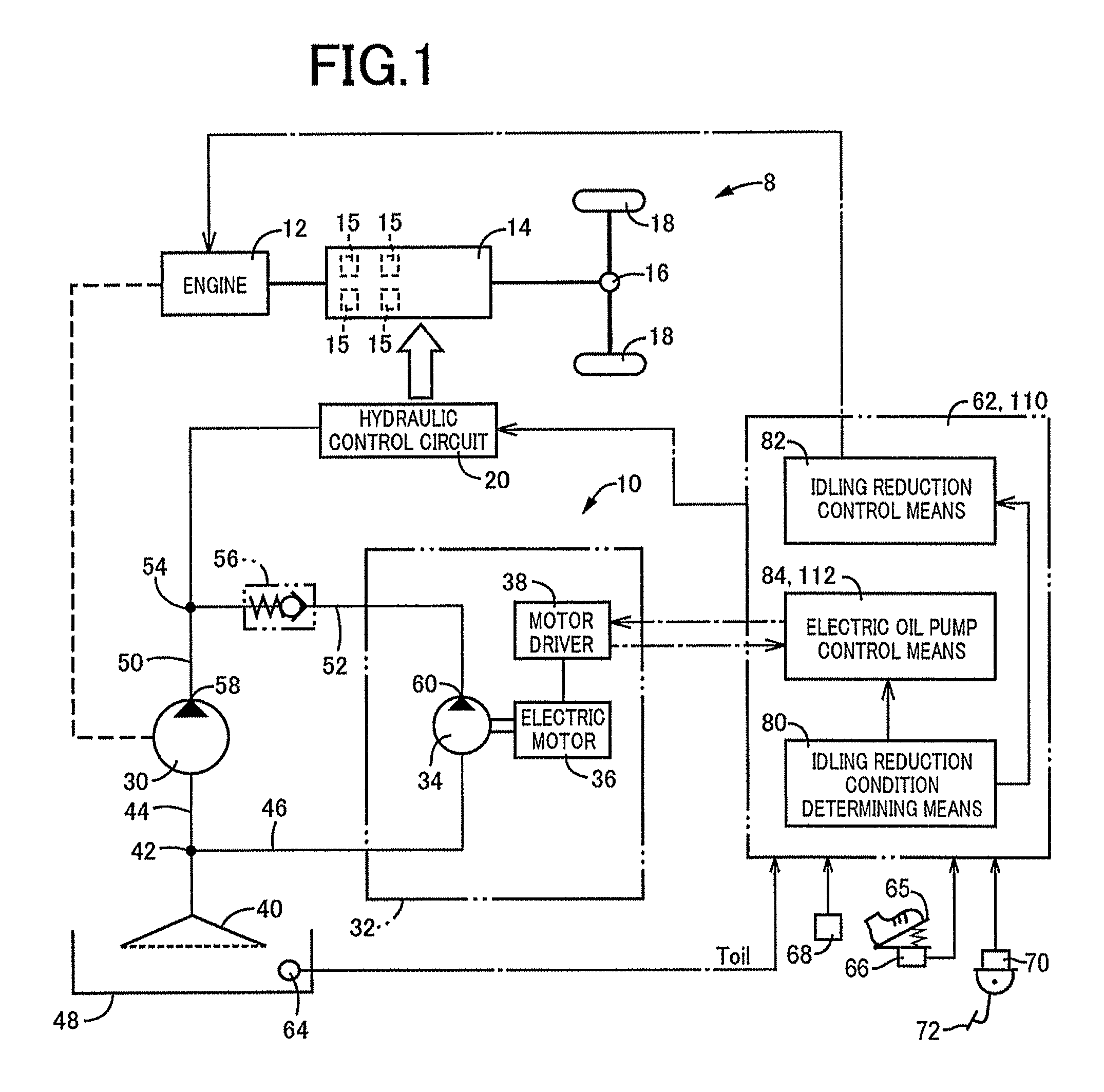
[0032]FIG. 1 is a block diagram of a outlined configuration of a vehicle 8 including a vehicle oil supply device 10 (hereinafter referred to as an oil supply device 10) that is an embodiment of the present invention. In FIG. 1, an engine 12 is an internal combustion engine such as a gasoline engine and a diesel engine and is cranked by a starter motor at the start of the engine to act as a power source for running. The output of the engine 12 is transmitted from an automatic transmission 14 via a differential gear device 16 to left and right drive wheels 18. The automatic transmission 14 corresponds to a power transmission mechanism and is a planetary gear type or a parallel shaft type stepped transmission including a plurality of friction engagement devices 15 (clutches and brakes) each engaged by a hydraulic actuator for switching a plurality of gear stages having different gear ratios. A hydraulic control circuit 20 is configured with an electromagnetic opening / closing valve, an ...

embodiment 2

[0073]In the description of this embodiment (second embodiment), differences from the first embodiment will mainly be described. A functional block diagram for explaining a main portion of the control function of an electronic control device 110 of this embodiment is FIG. 1, which is in common with the first embodiment; however, the electronic control device 110 includes an electric oil pump control means 112 instead of the electric oil pump control means 84 included in the electronic control device 62 of the first example. Therefore, the electronic control device 110 depicted in FIG. 1 includes the idling reduction condition determining means 80, the idling reduction control means 82, and the electric oil pump control means 112.

[0074]The electric oil pump control means 112 drives the electric motor 36 through the constant drive current control as is the case with the electric oil pump control means 84 of the first embodiment. However, the electric oil pump control means 112 is diff...


PUM


Abstract

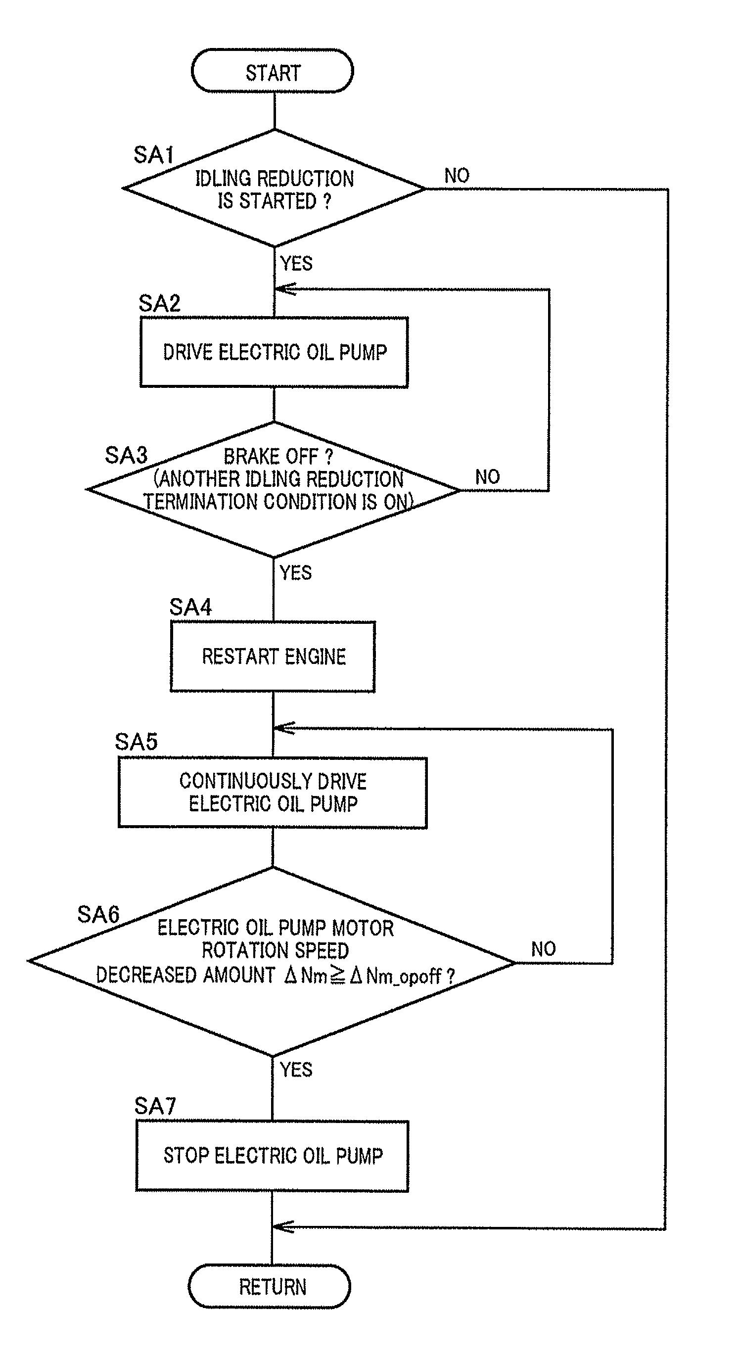
A control device has a mechanical oil pump driven by an engine and an electric oil pump supplying oil via a check valve in an oil passage connecting the mechanical oil pump and the electric oil pump, the check valve allowing a flow of the oil from the electric oil pump side to the mechanical oil pump side while blocking a flow in an opposite direction, regardless of the pressure of the electric oil pump. When the check valve is closed under an oil pressure condition in which the electric oil pump outputs a maximum output oil pressure while the mechanical oil pump is driven by the engine at idle, the control device is configured to drive the electric oil pump during stop of the mechanical oil pump, and to stop the electric oil pump based on a load increase after start of the mechanical oil pump.

Description

TECHNICAL FIELD[0001]The present invention relates to control for stopping an electric oil pump in a vehicle oil supply device including the electric oil pump and a mechanical oil pump.BACKGROUND ART[0002]A control device of a vehicle oil supply device has hitherto been known that includes an electric oil pump and a mechanical oil pump driven by an engine to supply oil to an oil supply destination. For example, this corresponds to an electric oil pump driving control device of a vehicle described in Patent Document 1. The vehicle described in Patent Document 1 provides idling reduction control for temporarily automatically stopping the engine in association with a stop of running of the vehicle. Since the mechanical oil pump is stopped as the engine stops during the idling reduction control, the electric oil pump driving control device drives the electric oil pump so as to supply oil to an automatic transmission etc. When the idling reduction control is canceled, the electric oil pu...

Claims


Application Information

Patent Timeline
Patent Type & Authority Patents(United States)
IPC IPC(8): F01M1/02F01M1/12F01M1/16F02D29/02F16H61/00
CPCF01M1/02F02D29/02F01M1/16F16H61/0031F01M2001/0215F01M2001/123F16H2312/14Y10T477/23
Inventor KARASAWA, MASAHIRO
Owner TOYOTA JIDOSHA KK
Learn More