High efficiency permanent magnet machine

a permanent magnet machine, high-efficiency technology, applied in the direction of electronic commutation motor control, magnetic circuit rotating parts, magnetic circuit shape/form/construction, etc., can solve the problems of increased size and weight, decreased efficiency, and undesirable copper losses, so as to reduce the magnetic saturation, increase efficiency, and increase the accuracy of field oriented control

Active Publication Date: 2014-09-09
UNIV OF CENT FLORIDA RES FOUND INC
View PDF9 Cites 1 Cited by
  • Summary
  • Abstract
  • Description
  • Claims
  • Application Information

AI Technical Summary

Benefits of technology

[0021]In a certain embodiment the stator teeth each have a generally uniform width, wherein the magnitude of the width is between about 60 and about 80 percent of the magnitude of the slot pitch. This design feature provides decreased magnetic saturation and therefore increased efficiency.
[0022]In a certain embodiment the present invention may utilize a sensorless field oriented control, where a rotor angle is estimated by a sliding mode observer and the sliding mode observer module contains a first order low-pass filter for back electromotive force estimation. In such an embodiment a phase lag compensation value, that is automatically calculated based on rotational speed of the rotor, is applied to feedback resulting in increased accuracy of the field oriented control.

Problems solved by technology

Traditionally in electric machine applications, the higher the electric machine's efficiency, the less energy wasted and the easier the thermal management system; however, the efficiency generally comes at the cost of increased size and weight.
Copper losses are an undesirable transfer of energy, as are core losses, which result from induced currents in adjacent components.
If the tooth size decreases, the magnetic saturation increases, and so the current must increase resulting in decreased efficiency.
Furthermore, where a definition or use of a term in a reference, which is incorporated by reference herein, is inconsistent or contrary to the definition of that term provided herein, the definition of that term provided herein applies and the definition of that term in the reference does not apply.

Method used


Image

  • High efficiency permanent magnet machine
  • High efficiency permanent magnet machine
  • High efficiency permanent magnet machine

Examples


example 1

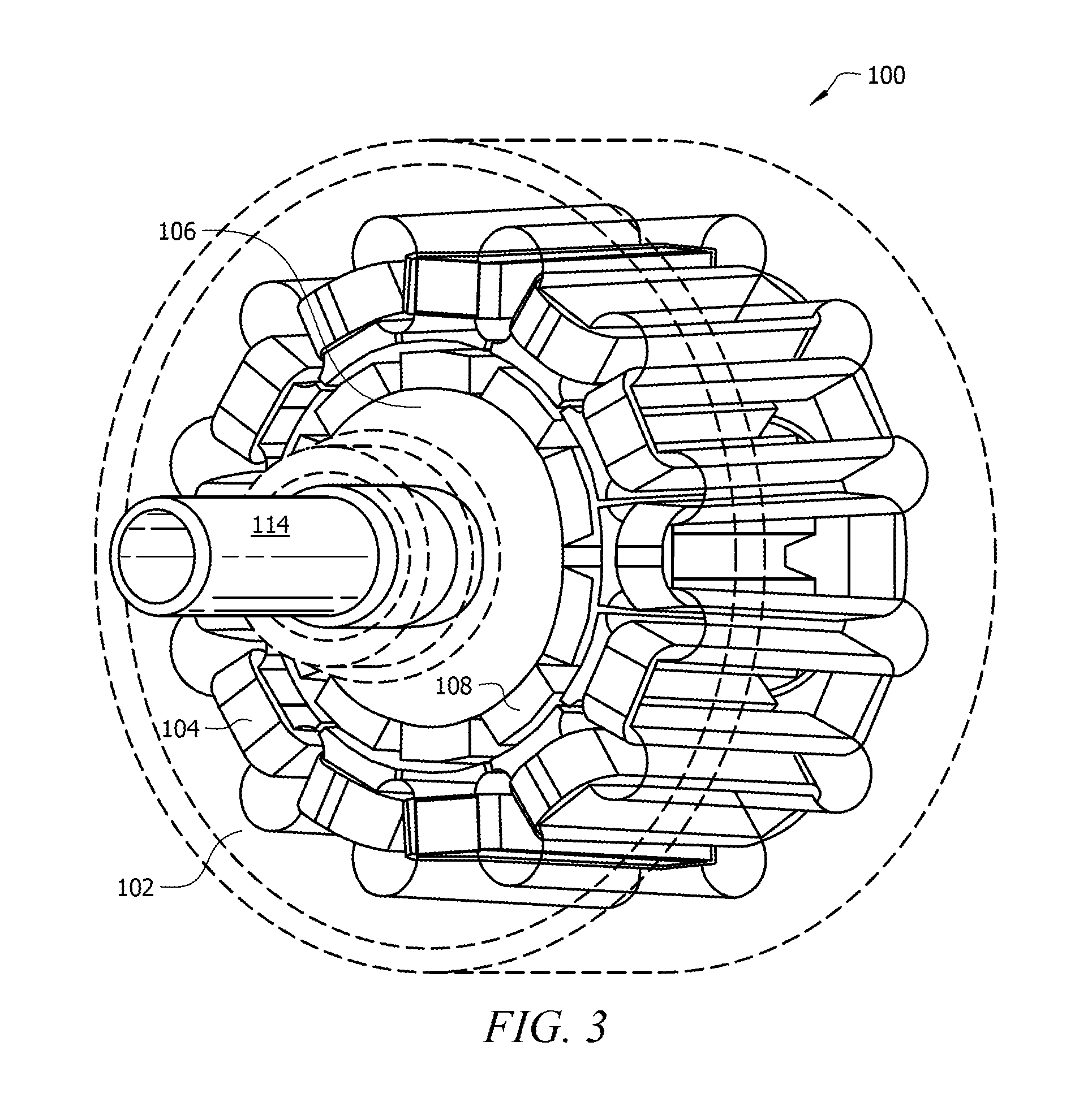
[0065]As shown in FIG. 3, a certain embodiment, generally denoted as reference numeral 100, of the present invention is a high efficiency electrical motor having shaft 114, laminated stator 102, and laminated rotor 106 all contained within housing 112. Laminated stator 102 contains a plurality of windings 104, and laminated rotor 106 contains a plurality of permanent magnets 108. Rotor 106 is disposed within the inner circumference of stator 102 such that the longitudinal axis of stator 102 is aligned with the central axis of rotor 106 and rotor 106 is freely rotatable within stator 102. Stator 102 has a plurality of stator teeth 110 and a plurality of stator slots wherein each stator slot is disposed between two stator teeth 110. Windings 104 are positioned around each tooth 110 passing through stator slots on either side of each respective tooth 110. Windings 104 are illustrated in the figures as having a rectangular shape for clarity purposes. The windings, being composed of mult...

example 2

[0070]As shown in FIG. 5, a certain embodiment, generally denoted as reference numeral 200, is a high efficiency electrical generator. Similar to the motor, the generator design includes shaft 214, stator 202, rotor 206, electrical windings 204, and PMs 208 all contained in housing 212. The rotor has four PMs 208 for use at a desired operational speed of 6,000 rpm to prevent excessive electrical frequency associated with too many rotor poles. Stator 202 is comprised of thirty six stator teeth 210 and therefore thirty six stator slots. Similar to windings 104, windings 204 are illustrated in the figures as having a rectangular shape for clarity purposes. As shown in FIG. 5, a winding encompasses two stator teeth. This illustration is simply for clarity. Embodiment 200 actually contains 2 coils per slot. FIGS. 11-14 illustrate the three phase winding diagram, in which there is 1 turn per coil, 2 coils per slot, and all the groups are connected in series. Each coil contains about 120 s...


PUM


Abstract

The present invention is a high efficiency permanent magnet machine capable of maintaining high power density. The machine is operable over a wide range of power output. The improved efficiency is due in part to copper wires with a current density lower than traditional designs and larger permanent magnets coupled with a large air gap. In a certain embodiment wide stator teeth are used to provide additional improved efficiency through significantly reducing magnetic saturation resulting in lower current. The machine also has a much smaller torque angle than that in traditional design at rated load and thus has a higher overload handling capability and improved efficiency. In addition, when the machine is used as a motor, an adaptive phase lag compensation scheme helps the sensorless field oriented control (FOC) scheme to perform more accurately.

Description

CROSS-REFERENCE TO RELATED APPLICATIONS[0001]This nonprovisional application claims priority to provisional application No. 61 / 748,998, entitled “HIGH EFFICIENCY LOW SPEED PERMANENT MAGNET MACHINE,” filed Jan. 4, 2013, and to provisional application No. 61 / 803,993 entitled “High Efficiency Permanent Magnet Machine,” filed Mar. 21, 2013.BACKGROUND OF THE INVENTION[0002]1. Field of the Invention[0003]This invention relates, generally, to electrical machines. More specifically, it relates to a high efficiency electrical motor or generator.[0004]2. Brief Description of the Prior Art[0005]Electrical motors and generators are machines capable of converting electrical energy into mechanical energy and converting mechanical energy into electrical energy, respectively. These electrical machines have many similarities and can often be operated as either an electrical generator or motor.[0006]Known electrical machines include a rotor, a stator, a plurality of electrical windings, and a plurali...

Claims


Application Information

Patent Timeline
Patent Type & Authority Patents(United States)
IPC IPC(8): H02K1/27H02K1/14H02K9/00
CPCH02K1/274H02K9/00H02K2213/03H02P6/182H02P6/145H02K3/12H02K1/16H02K21/16H02K3/28H02K21/14H02P6/153
Inventor WU, XINZHANGLIU, HANZHOUHU, YANGCHOW, LOUISHARMS, JONEPSTEIN, MARTINWU, WEI
Owner UNIV OF CENT FLORIDA RES FOUND INC
Why Eureka
Try Eureka