Induction type magnetic suspension momentum sphere device

A magnetic levitation, momentum ball technology, applied in the field of aircraft attitude control, can solve the problems of angular momentum adjustment, limited control ability, rotor speed limit, prone to magnetic saturation, etc.

Inactive Publication Date: 2020-12-01
NINGBO INST OF MATERIALS TECH & ENG CHINESE ACADEMY OF SCI
View PDF5 Cites 2 Cited by
  • Summary
  • Abstract
  • Description
  • Claims
  • Application Information

AI Technical Summary

Problems solved by technology

The existing momentum balls are mainly divided into induction type, permanent magnet type, hysteresis type, reluctance type, ultrasonic type and moving wheel type. Among them, the spherical motor of the permanent magnet type momentum ball has high efficiency, but the control strategy is complicated and the reliability is low. Low; the structure of the hysteresis momentum ball is simple and reliable, but the torque density is low and the volume is large; the structure of the reluctance momentum ball is firm, but there is torque ripple, and the suspension control is difficult; the ultrasonic momentum ball is easy to realize small However, because the rotor is driven by friction, the rotor speed is greatly limited; the moving wheel momentum ball is independently controlled by multiple single-axis motors, but multiple motors will bring additional mass and volume; and the more widely used induction Type momentum ball, its diagonal momentum adjustment and control capabilities are limited, its torque is small, electromagnetic interference is relatively serious, and magnetic saturation is prone to occur, which affects the speed performance

Method used


Image

  • Induction type magnetic suspension momentum sphere device
  • Induction type magnetic suspension momentum sphere device
  • Induction type magnetic suspension momentum sphere device

Examples


Embodiment Construction

[0029] In order to facilitate the understanding of the present invention, the present invention will be described more fully below with reference to the associated drawings. Preferred embodiments of the invention are shown in the accompanying drawings. However, the present invention can be embodied in many different forms and is not limited to the embodiments described herein. On the contrary, these embodiments are provided to make the understanding of the disclosure of the present invention more thorough and comprehensive.

[0030] It should be noted that when an element is considered to be "connected" to another element, it may be directly connected to the other element or there may be intervening elements at the same time. Unless otherwise defined, all technical and scientific terms used herein have the same meaning as commonly understood by one of ordinary skill in the technical field of the invention. The terms used herein in the description of the present invention are...


PUM


Abstract

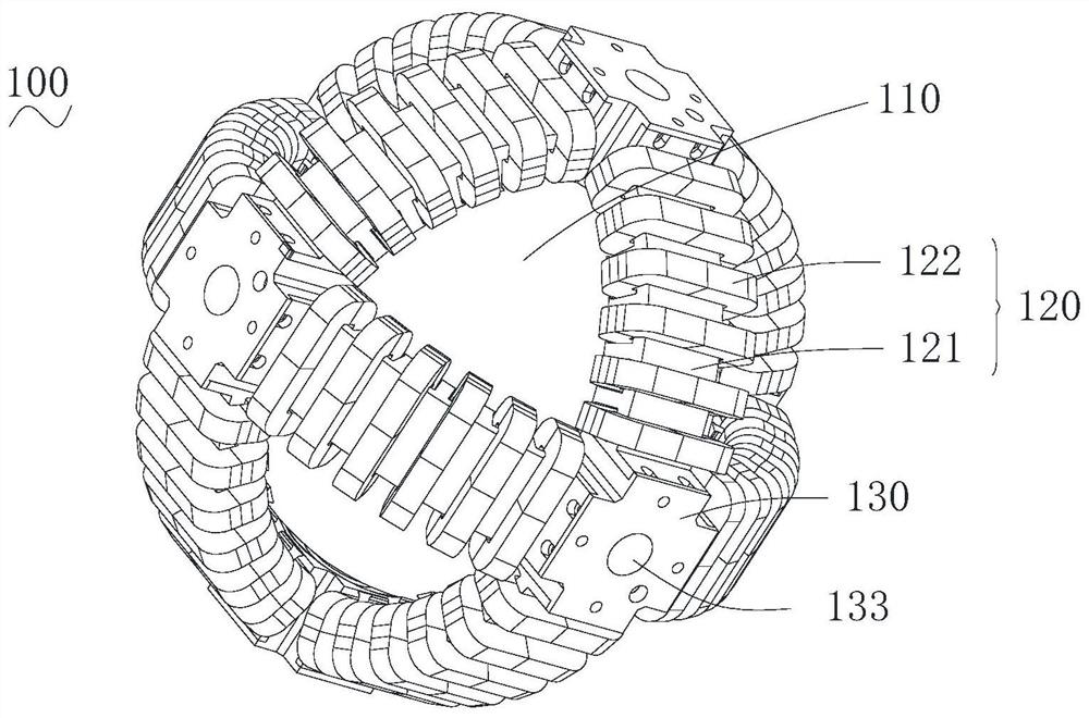
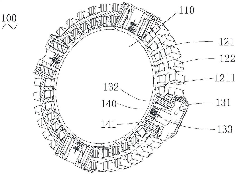
The invention provides an induction type magnetic suspension momentum sphere device. The device comprises a spherical rotor; a plurality of torque assemblies which are arranged outside the spherical rotor and are used for generating a rotating magnetic field; a plurality of suspension assemblies which are connected among the plurality of torque assemblies, wherein the suspension assemblies and thetorque assemblies are arranged at intervals, and two or more intersected closed loops are formed; and a controller. According to the induction type magnetic suspension momentum sphere device, two ormore intersected closed loops are formed by the torque assemblies and the suspension assemblies, and the structure is simple and reliable; each closed loop enables the edge position of each torque assembly to generate effective torque, the induced eddy current generated on the surface of the spherical rotor is more fully utilized, and the output torque can be increased; the torque assemblies and the suspension assemblies are arranged at intervals, a torque magnetic field and a magnetic suspension magnetic field act on different positions, and the risk of magnetic saturation is reduced; and thetorque assemblies and the suspension assemblies are relatively independent so that maintenance and replacement are easier when a fault occurs.

Description

technical field [0001] The invention relates to the technical field of aircraft attitude control, in particular to an inductive magnetic levitation momentum ball device. Background technique [0002] The aircraft will be affected by various disturbance moments during flight, which will cause the attitude of the aircraft to change, so the attitude control must be carried out. The commonly used one is the angular momentum exchange system, including "single degree of freedom system" and "multiple degree of freedom system". [0003] Each degree of freedom of the "single-degree-of-freedom system" can only adjust the attitude in one direction, such as the reaction flywheel, in order to ensure that the three degrees of freedom can be adjusted at least three sets of reaction flywheel devices are required, and there will be a coupling effect between the three flywheels, so A nonlinear control strategy is needed to decouple it. In addition, an additional flywheel is required for sys...

Claims


Application Information

Patent Timeline
IPC IPC(8): B64G1/28
CPCB64G1/285B64G1/245
Inventor 张杰袁黎明陈进华张驰梁雨生
Owner NINGBO INST OF MATERIALS TECH & ENG CHINESE ACADEMY OF SCI
Why Eureka
Try Eureka