
Apparatus and methods for electrostatically producing dye-printed material

a technology of electrostatic production and printed materials, which is applied in the direction of dyeing process, electrographic process, instruments, etc., can solve the problems of poor transfer effect of liquid toner in methods using liquid toner, insufficient clarity, and difficulty in transferring toner to the recessed sections, etc., and achieves high image transfer

Inactive Publication Date: 2014-08-05
KYOTO MUNICIPAL INST OF IND TECH & CULTURE
View PDF34 Cites 11 Cited by
  • Summary
  • Abstract
  • Description
  • Claims
  • Application Information

AI Technical Summary

Benefits of technology

[0023]According to one or more embodiments of the present invention, the dry toner is transferred by flying. Therefore, a high transfer property of the dry toner can be realized regardless of the state of the surface of the base material, and a clear image can be printed (fixed).
[0029]As a result of these, for example, disproportionate application of the dry toner to a most-projected section or the like of the base material can be prevented, and a good image with little density unevenness can be reproduced on the base material.
[0031]In that case, penetration of the dry toner through the fabric can be prevented, and stains of the belt and the waste of the dry toner can be prevented.
[0033]According to this, images of various shapes can be easily formed by the toner.
[0035]As a result, the binder can be easily removed in a subsequent step, and a base material, such as a fabric, with a good handle can be obtained.
[0043]According to one or more embodiments of the present invention, a clear printed material and a dye-printed material with a high transfer property of image can be obtained regardless of the state of the surface of a base material.

Problems solved by technology

By the way, among the dye-printing methods using an electrophotographic system, a property of transfer from a photoreceptor to a base material, such as a fabric, is poor in methods using a liquid toner (for example, Patent Literatures 5 and 6).
For example, in a base material, such as a fabric, with projections and recesses on the surface due to weave pattern, mesh, embossing, or the like for design, although the toner is actively transferred to the projected sections, it is difficult to transfer the toner to the recessed sections, and the clarity tends to be insufficient.
However, in the methods of Patent Literatures 7 and 8, for example, although the toner is actively transferred to the projected sections in a base material, such as a fabric, with projected and recessed sections on the surface, it is difficult to transfer the toner to the recessed sections, and the clarity tends to be insufficient.

Method used


Image

  • Apparatus and methods for electrostatically producing dye-printed material
  • Apparatus and methods for electrostatically producing dye-printed material
  • Apparatus and methods for electrostatically producing dye-printed material

Examples


first embodiment

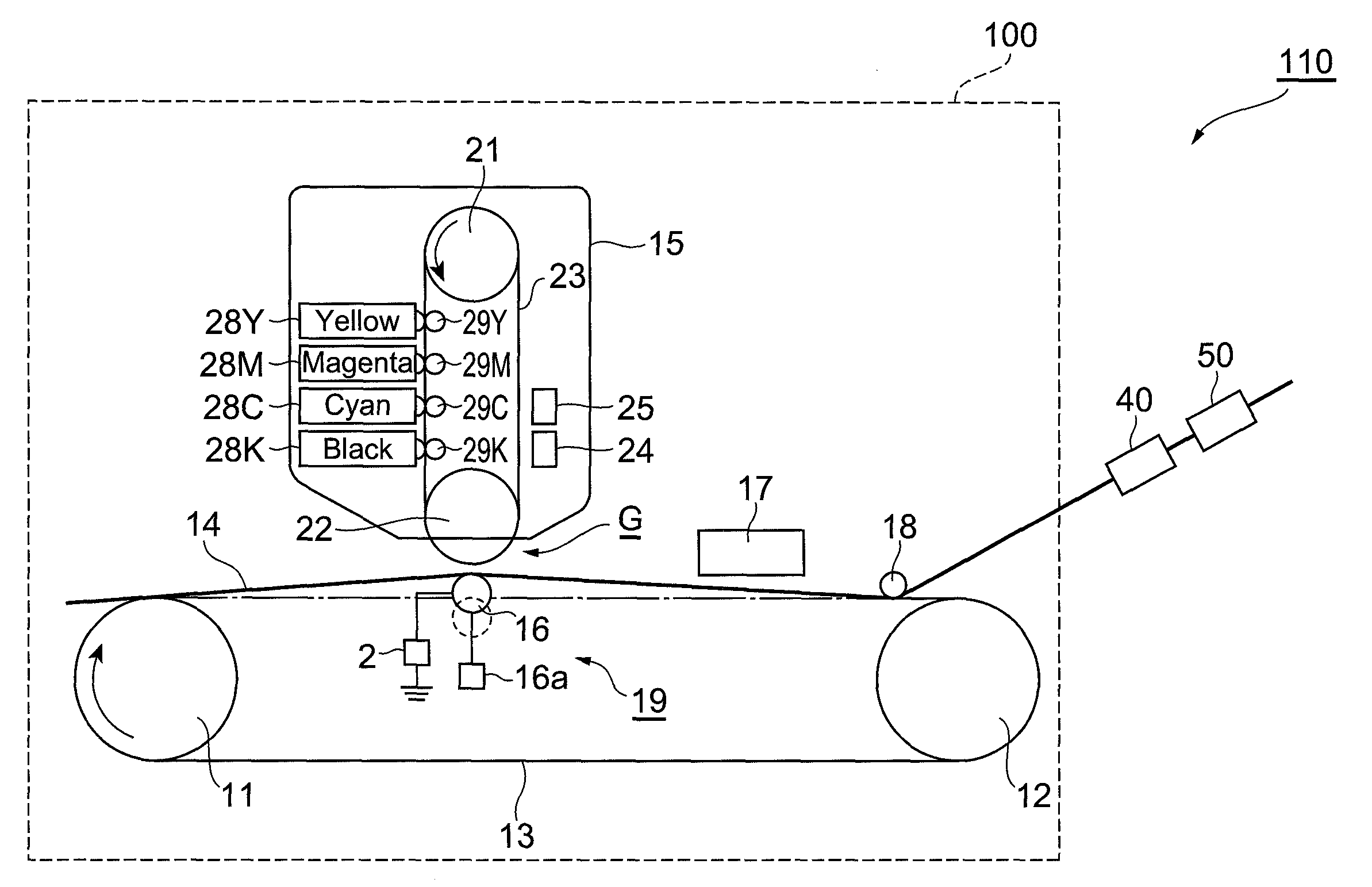
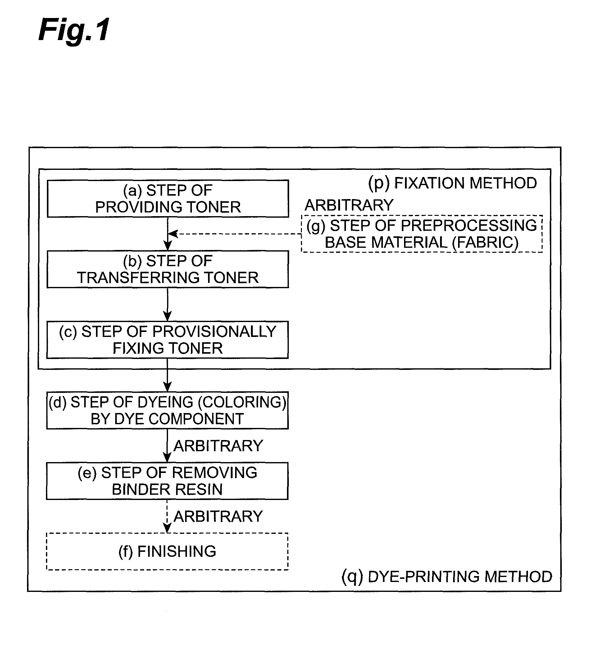
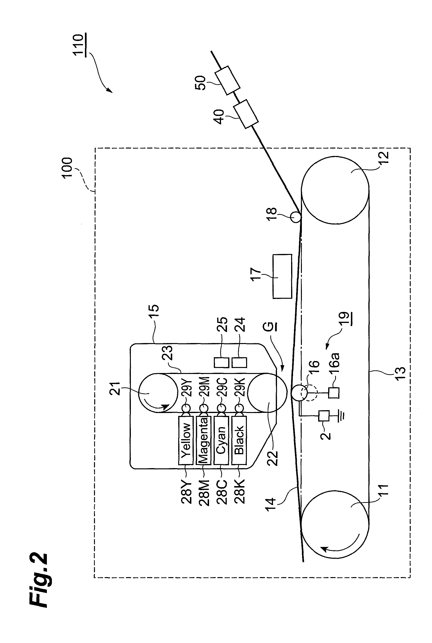
[0056]FIG. 1 is a diagram schematically showing a process chart for explaining an example of working steps for carrying out a method (p) for producing a printed material and a method (q) for producing a dye-printed material according to the embodiments of the present invention.

[0057]As shown in FIG. 1, in the present embodiment, the method (p) for producing a printed material includes a step (a) of electrostatically providing dry toner particles to a charged body, a step (b) of electrostatically transferring a dry toner from the charged body to a base material, and a step (c) of provisionally fixing the dry toner particles transferred to the base material to the base material. As a result, a base material including the toner particles fixed to the base material (hereinafter, may be called “printed material” (fixed material)) can be obtained. In addition, the method (q) for producing a dye-printed material in the present embodiment further includes a step (d) of dyeing the base mater...

second embodiment

[0124]Next, a printing apparatus 200 and a dye-printing system 220 according to a second embodiment will be described with reference to FIG. 9. The printing apparatus 200 of FIG. 9 can also perform printing by the four-color collective transfer system. Hereinafter, only the points different from the printing apparatus 100 will be described, and the description of the same parts will not be repeated. The printing apparatus 200 includes a four-color imaging unit (electrostatic holding unit) 15A that forms an image to be transferred to the base material 14 and a transfer unit 70A.

[0125]The four-color imaging unit 15A includes pulleys 21A and 22A arranged above and below and a photoreceptor belt 23A wound between the pulleys. Between the pulleys 21A and 22A, the cleaning apparatus 24 that removes an attachment on the photoreceptor belt 23A, the electricity removal apparatus 25 that removes electricity of the photoreceptor belt 23A, a charging apparatus 26 that charges the photoreceptor ...

third embodiment

[0135]FIG. 10 is a schematic diagram showing a printing apparatus 300 and a dye-printing system 310 according to still another third embodiment of the present invention. The printing apparatus 300 of FIG. 10 can also perform dye-printing by the four-color collective transfer system. Hereinafter, only the points different from the printing apparatus 100 of FIG. 2 will be described, and the description of the same parts will not be repeated. In the printing apparatus 300, monochromatic imaging units (electrostatic holding units) 15YB, 15MB, 15CB, and 15KB that form monochromatic images of yellow, magenta, cyan, and black are arranged in tandem on the conveying belt 13.

[0136]For example, the monochromatic imaging unit 15YB includes pulleys 21B and 22B arranged above and below and a photoreceptor belt (charged body) 23B wound between the pulleys. Between the pulleys 21B and 22B, a cleaning apparatus 24B that removes an attachment on the photoreceptor belt 23B, an electricity removal app...


PUM

PropertyMeasurementUnit
temperatureaaaaaaaaaa
particle sizeaaaaaaaaaa
thicknessaaaaaaaaaa

Abstract

A method for producing a printed material, a method for producing a dye-printed material, a printing apparatus, and a dye-printing system have a good transfer property when a dry toner including a dye is electrostatically transferred to a base material, such as a fabric, based on an electrophotographic system or the like. The methods include a step of providing at least one type of dry toner containing a dye component and a binder resin to a charged body, a step of transferring the dry toner from the charged body to a base material, and a step of fixing the dry toner on the base material. In the transfer step, an electric field is applied between the charged body and the base material to fly the dry toner on the charged body from the charged body to the base material.

Description

TECHNICAL FIELD[0001]The present invention relates to a method for producing a printed material, a method for producing a dye-printed material, a printing apparatus, and a dye-printing system.BACKGROUND ART[0002]Dye-printing is applied to textile products of various forms, such as yarns, knit fabrics, and secondary products, and to other materials. As shown in Patent Literatures 1 to 8, various dye-printing techniques are known.[0003]Patent Literature 1: Japanese Patent Laid-Open No. 10-195776[0004]Patent Literature 2: Japanese Patent No. 2995135[0005]Patent Literature 3: Japanese Patent Laid-Open No. 2003-96340[0006]Patent Literature 4: Japanese Patent Laid-Open No. 7-278482[0007]Patent Literature 5: Japanese Patent Laid-Open No. 8-226083[0008]Patent Literature 6: Japanese Patent Laid-Open No. 9-73198[0009]Patent Literature 7: Japanese Patent Laid-Open No. 10-239916[0010]Patent Literature 8: Japanese Patent Laid-Open No. 5-027474[0011]Patent Literature 9: Japanese Patent Laid-Open ...

Claims


Application Information

Patent Timeline
Patent Type & Authority Patents(United States)
IPC IPC(8): G03G15/20
CPCG03G11/00D06P5/003D06P5/00G03G15/2007G03G7/0093G03G15/6588G03G9/08797G03G15/6591G03G9/08795D06P1/44D06P1/0004
Inventor OKAMOTO, KAZUMIHAYAMI, TADASHI
Owner KYOTO MUNICIPAL INST OF IND TECH & CULTURE
Learn More