
Engine idle speed control system and method for vehicular gear

a technology of idle speed control and engine, which is applied in the direction of engine starters, machines/engines, instruments, etc., can solve the problems of engine wear, engine idle speed control system or apparatus not available for conventional shifting motorcycles, and the throttle position cannot be directly sensed to implement the idle speed control mechanism, etc., to achieve optimal air fuel ratio, reduce fuel consumption, and reduce engine wear

Inactive Publication Date: 2014-07-22
KYMCO
View PDF4 Cites 3 Cited by
  • Summary
  • Abstract
  • Description
  • Claims
  • Application Information

AI Technical Summary

Benefits of technology

The system effectively reduces fuel consumption, minimizes engine wear, and enhances safety by allowing the engine to start at optimal air-fuel ratios without sudden throttle operations, preventing unexpected acceleration or engine stop, thus improving rider safety.

Problems solved by technology

However, no relevant techniques such as an idle speed control system or apparatus is available for the conventional shifting motorcycle.
The architecture of the clutch and the gear of the vehicle requires the rider to control and switch gears, so the throttle position cannot be directly sensed to implement the idle speed control mechanism as the conventional shifting motorcycle.
Next, in the action of starting the engine through the throttle operation, the air intake amount of the engine changes with the throttle position which is different from the start mode that the throttle is preset to be off, so the engine cannot start at an optimal air fuel ratio.
On the contrary, the fuel consumption is increased and meanwhile the engine is worn and not easy to start.
Also, if the throttle operation of the vehicle is excessively large, when the engine is being started, unexpected dangers such as sudden acceleration, engine stop, part burnout may occur, which result in dangers to the rider.

Method used


Image

  • Engine idle speed control system and method for vehicular gear
  • Engine idle speed control system and method for vehicular gear
  • Engine idle speed control system and method for vehicular gear

Examples


Embodiment Construction

[0037]The embodiments of the present invention are illustrated in detail with reference to the accompanying drawings as follows.

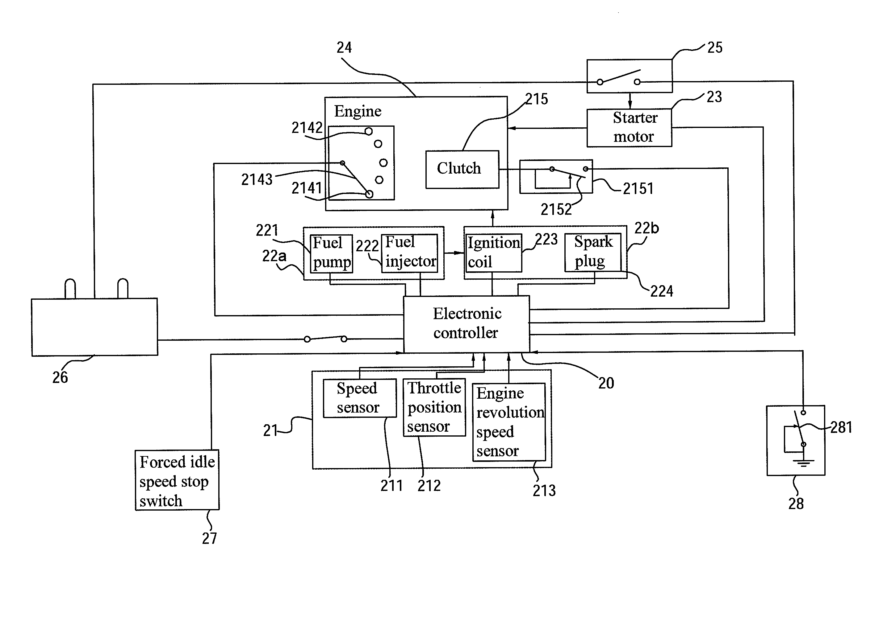
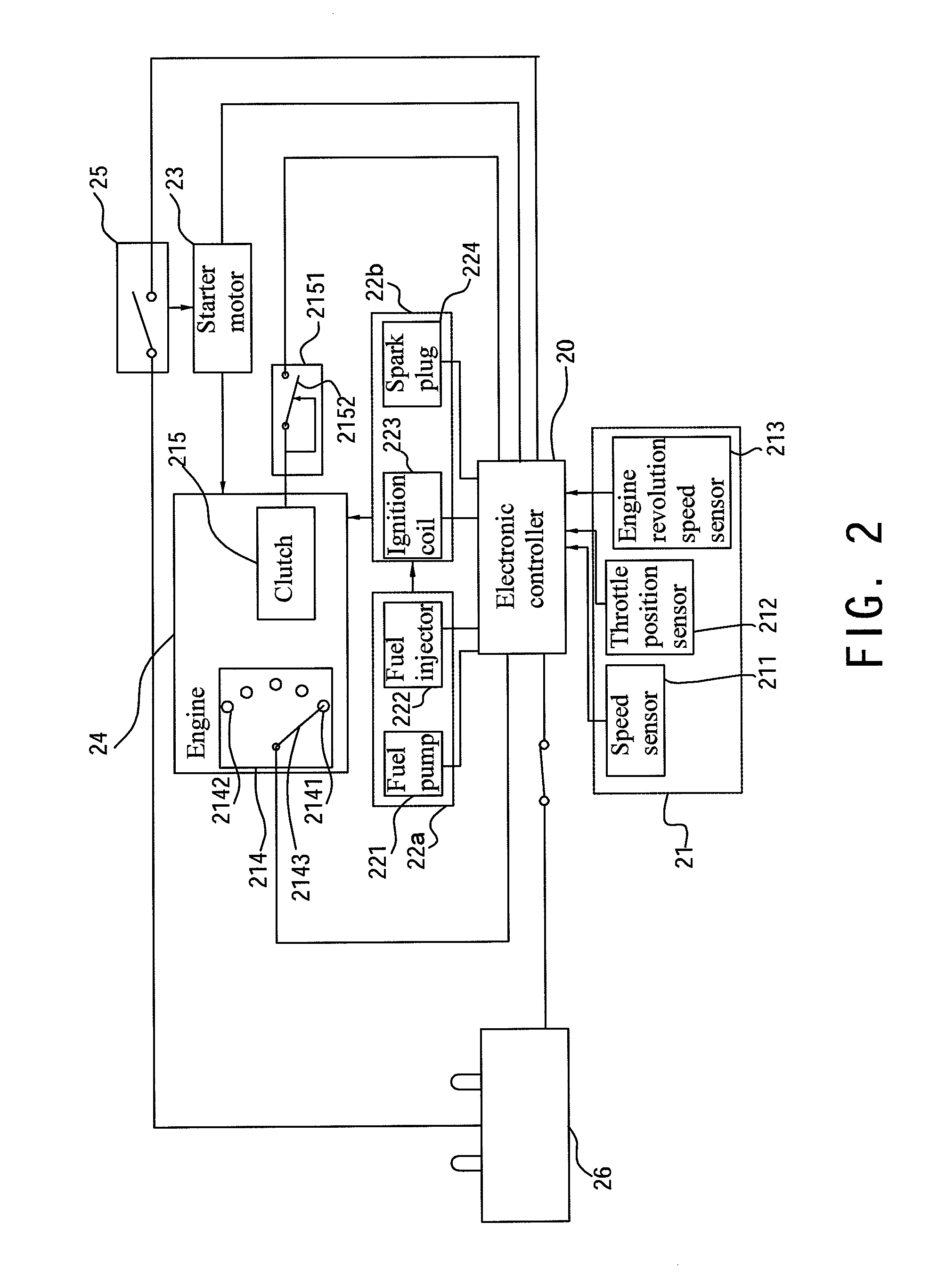
[0038]FIG. 2 is a schematic view of a first architecture of an engine idle speed control system for the vehicular gear according to an embodiment of the present invention and FIG. 3 is a schematic view of an architecture of circuit connection of an electronic controller according to an embodiment of the present invention. The electronic controller 20 controls and communicates with all electronic parts of the vehicle, and the electronic controller 20 is an electronic control unit (ECU) or relevant controllers.

[0039]A battery 26 of the vehicle is electrically connected to a starter switch 25, and the starter switch 25 is then electrically connected to a starter motor 23. An engine 24 of vehicle is connected to an ignition unit 22b, a fuel supply unit 22a and the starter motor 23. The engine 24 includes a gear mechanism 214 and a clutch 215. The clutch 215 is ...


PUM


Abstract

An engine idle speed control system and a method for a vehicular gear are provided. The system includes an electronic controller, an engine connected to an ignition unit and a fuel supply unit, a battery, a starter switch connected to the battery, and a starter motor connected to the starter switch. The engine has a gear mechanism and a clutch which is connected to a clutch lever. The electronic controller is connected to a vehicle speed sensor, a throttle position sensor, and an engine revolution speed sensor. The clutch lever with a node switch provides a lever node control signal, the gear mechanism with a gear node switch provides a gear node control signal, and the electronic controller is connected to the node switch of the clutch lever and the gear node switch of the gear mechanism, so as to control automatic idle speed stop and start of the engine.

Description

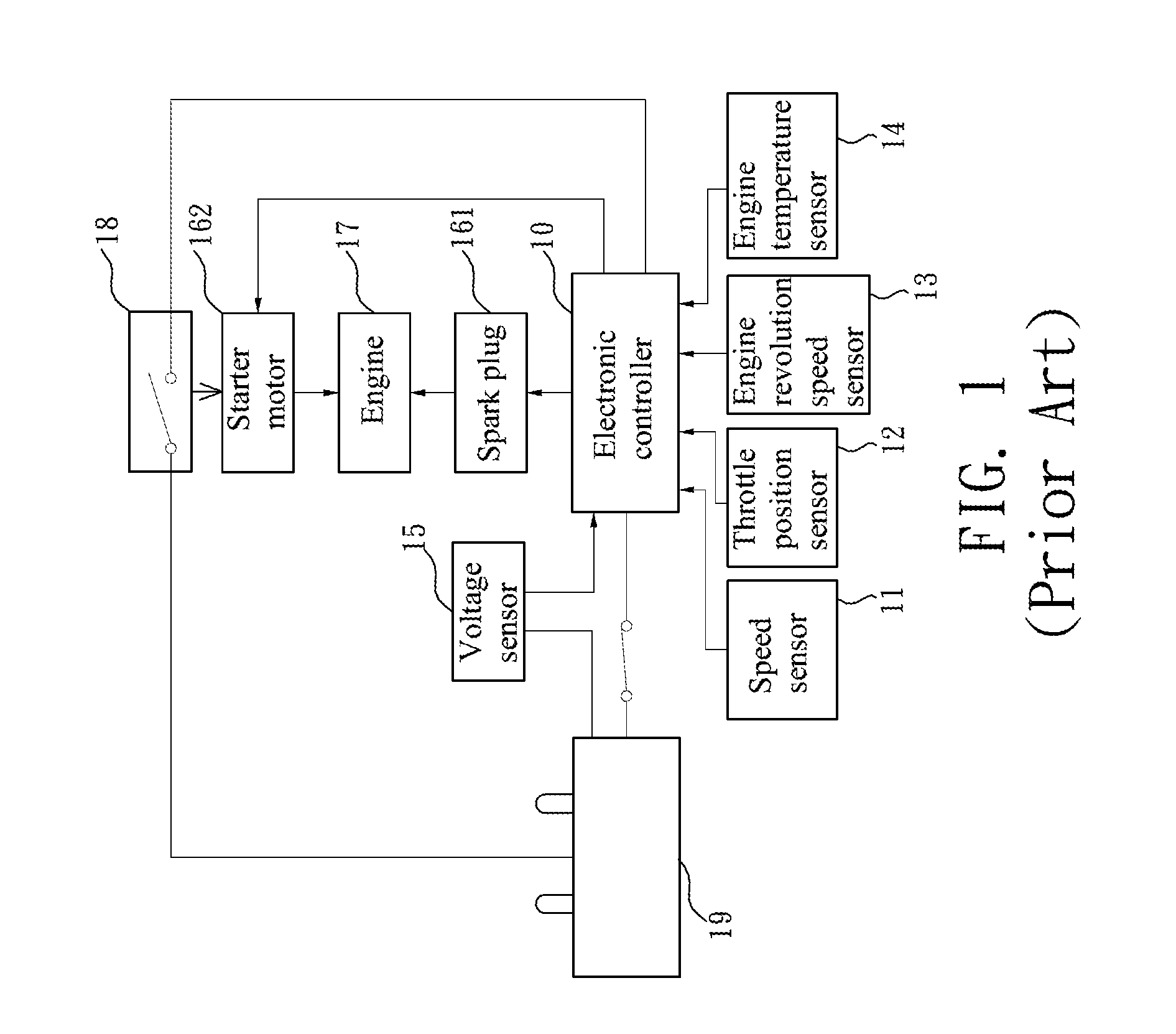
CROSS-REFERENCE TO RELATED APPLICATION[0001]This application claims the benefit of Taiwan Patent Application No. 099125161 filed on Jul. 29, 2010, which is hereby incorporated by reference for all purposes as if fully set forth herein.BACKGROUND OF THE INVENTION[0002]1. Field of Invention[0003]The present invention relates to an automotive engine idle speed control system and method, and more particularly to an engine idle speed control system and a method for a vehicular gear applicable to vehicular gear engines in which an idle speed system is combined with an electronic controller.[0004]2. Related Art[0005]FIG. 1 is a schematic view of an architecture of an idle speed control system for a motorcycle in the prior art. In the prior art, to reduce fuel consumption when the motorcycle pauses and to extend the use life of all parts, an idle speed control system is configured for the motorcycle.[0006]When a rider turns on a master key switch of the motorcycle so all parts are powered b...

Claims


Application Information

Patent Timeline
Patent Type & Authority Patents(United States)
IPC IPC(8): F02N11/08F02N11/00
CPCF02N11/0822B60W30/18018B60W2510/0208B60W2510/0604B60W2510/0638B60W2510/101B60W2520/10F02D2200/502F02N11/0833F02N2200/022F02N2200/023F02N2200/063F02N2200/0801F02N2200/0802F02N2200/0803F02N2200/103F02N2300/2011Y02T10/48F02N11/0825Y02T10/40
Inventor CHEN, CHUN-HSIUNG
Owner KYMCO
Learn More