Conveyer belt and apparatus

a conveyor belt and belt end technology, applied in the field of conveyor belts, can solve the problems of increased cost, insufficient flexibility for use as a conveyor belt, and yarn fraying at the belt side end, and achieve the effect of reducing the degree of elongation, stably conveying the object, and increasing the curvature of the loop

Active Publication Date: 2014-07-22
SHOJI SUSUMU +1
View PDF36 Cites 6 Cited by
  • Summary
  • Abstract
  • Description
  • Claims
  • Application Information

AI Technical Summary

Benefits of technology

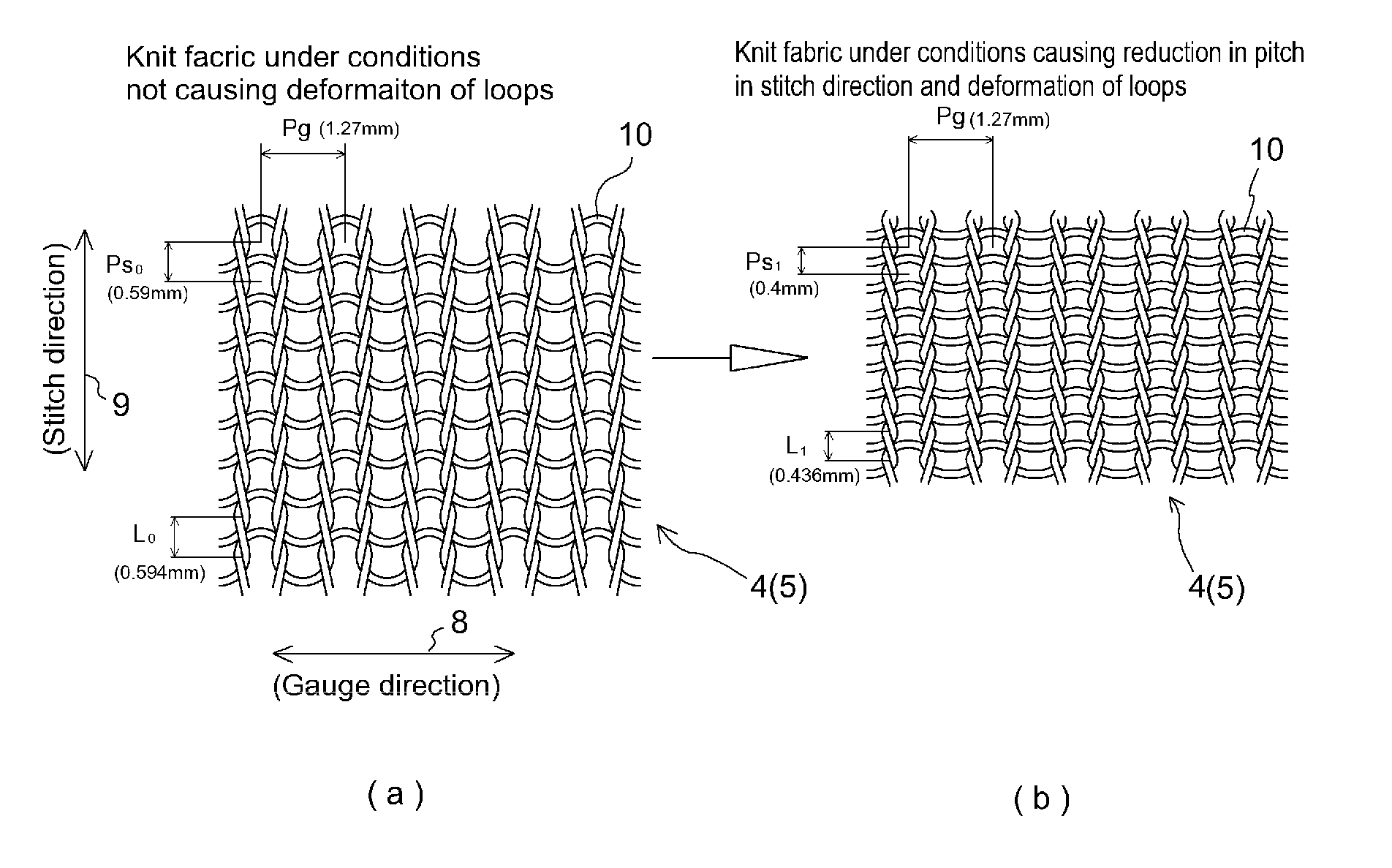
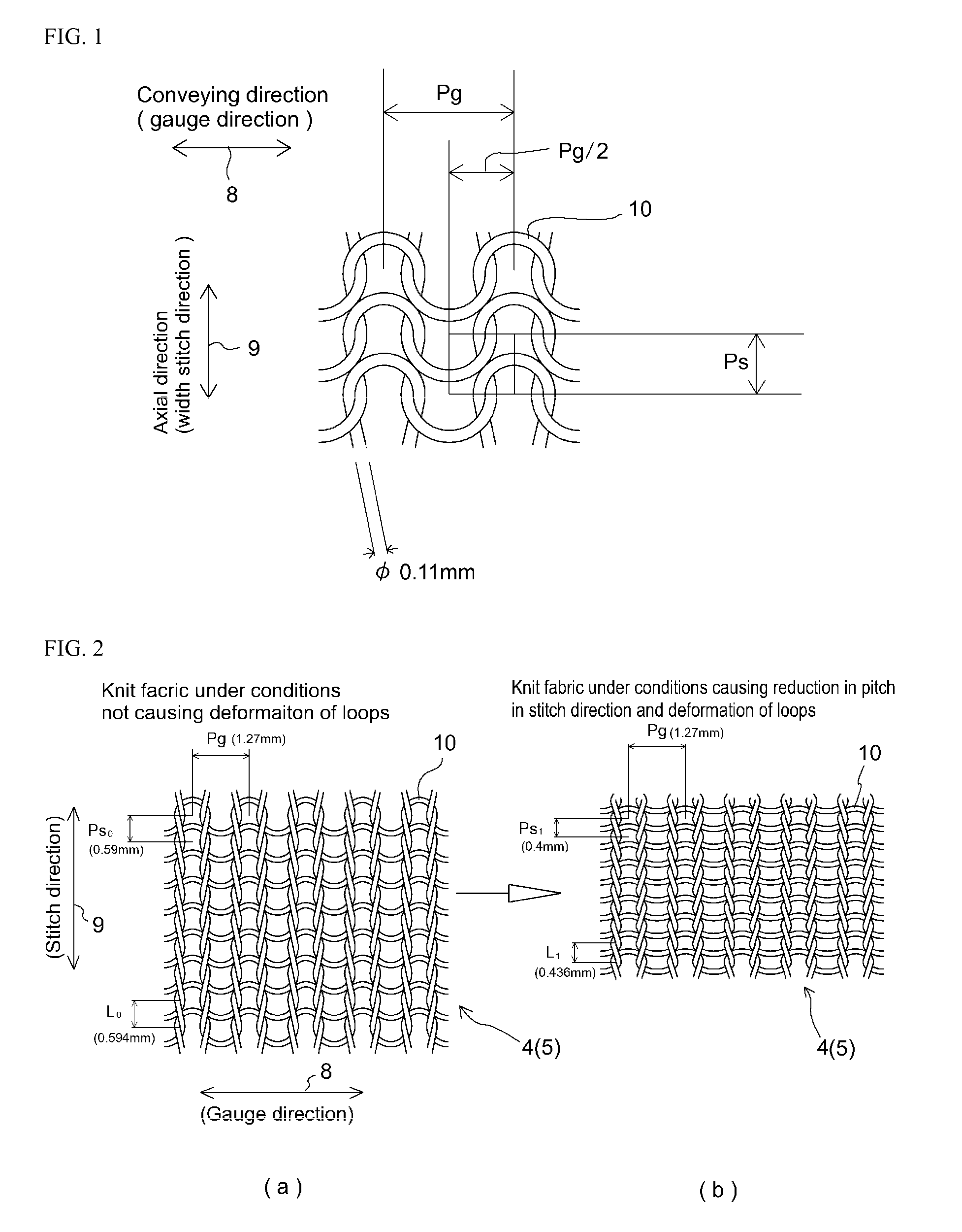
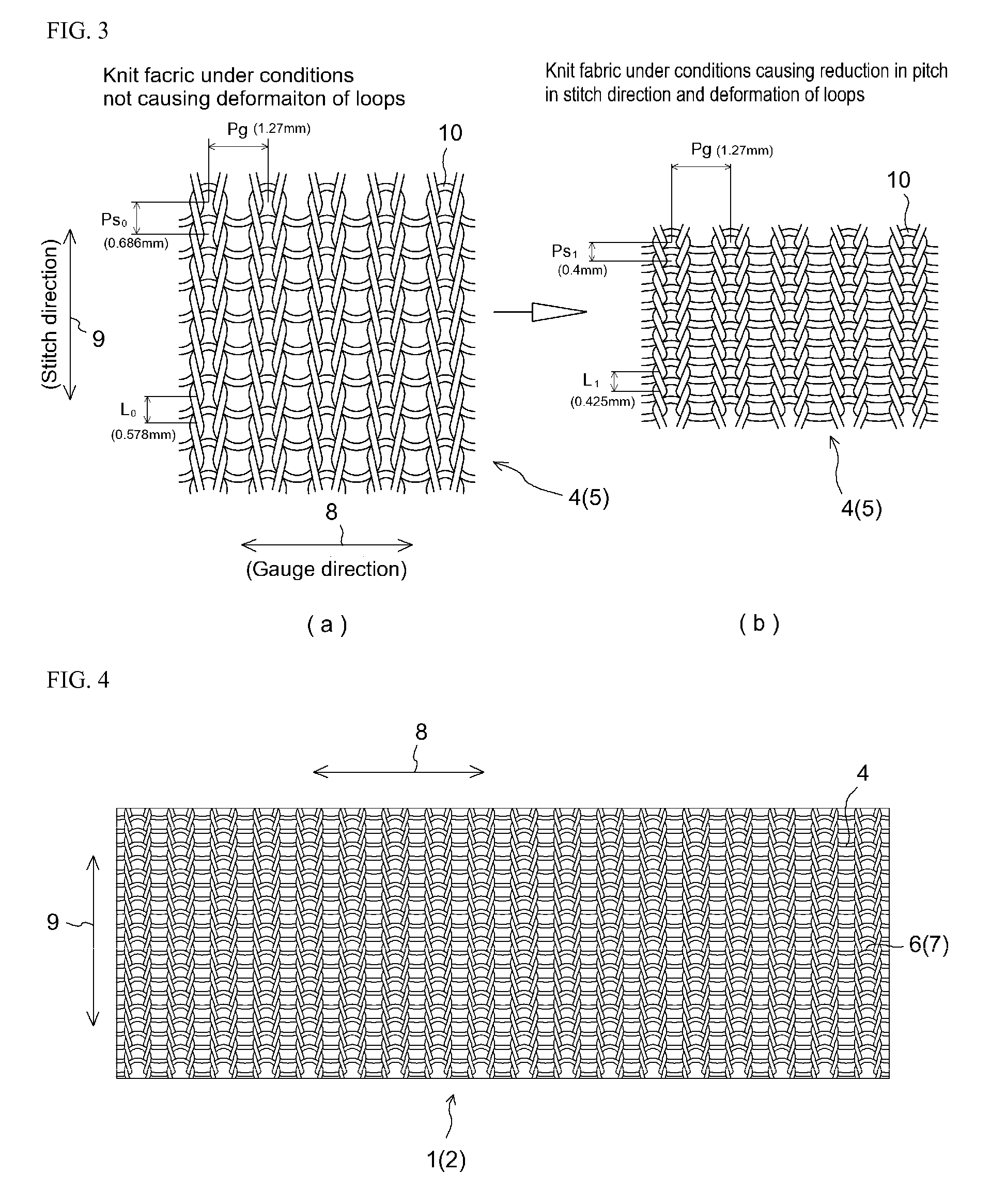
[0030]Of the means in accordance with the present invention for solving the foregoing problems, a first means is a conveyor belt comprising knit fabric and suited for when paper and sheet-like things or objects are to be conveyed at high speed by virtue of air permeability by suction of air, the conveyor belt being such that it comprises weft knit fabric; yarn from which the conveyor belt is formed is filament comprising synthetic continuous fiber; the yarn filament exhibits mutual intertwining; knit pattern is such that pitch of mesh loops in a stitch direction which is a width direction is smaller than pitch of mesh loops in a gauge direction which is a conveying direction; a state is maintained in which mutually contacting mesh loops are deformed and loop filament is entangled, strength being increased in the conveying direction as a result of mutual intertwining of filament; and strength is increased and fraying of yarn filament at belt side ends is prevented during conveying by the conveyor belt.
[0036]In accordance with the foregoing first means of the present invention, a structure is achieved in which there is no fraying of yarn at side ends of the conveyor belt. In accordance with the second means, because the yarn of the knit fabric from which the conveyor belt is formed is such that filament exhibiting plastic deformation as a result of exposure to a prescribed amount of heat is included among a plurality of filaments, flexural stress and a prescribed amount of heat cause the mesh loops which comprise this yarn to undergo plastic deformation and to be maintained in an entangled state such that curvature of loops is increased and the degree of change in elongation is reduced. Moreover, in accordance with the third means, because loops of knit fabric are formed from filament having a large coefficient of friction, the force with which the conveyor belt grips an object to be conveyed is increased, making it possible to stably convey the object to be conveyed. In accordance with the fourth means, because the filament having a large coefficient of friction is such that low-melting-point elastic filament is included within the plurality of filaments, thermal fusing or heat-setting causes still further increase in the force with which the conveyor belt grips an object to be conveyed, making it possible to more stably convey the object to be conveyed. In accordance with the fifth means, suppression of elongation in the conveying direction of the conveyor belt makes it possible to inhibit meandering of the conveyor belt. In accordance with the sixth means, because a belt according to the first means through the fifth means has been adapted for use as a conveyor belt within the apparatus interior at a conveyor apparatus, it will be possible in the context of this conveyor apparatus to stably convey an object to be conveyed such that the belt operates smoothly at the apparatus interior without occurrence of meandering.

Problems solved by technology

However, the foregoing proposed conveyor belts which comprise mesh belts have the problem that fraying of yarn occurs at the belt side ends, processing being implemented at the belt side ends in the foregoing Patent Reference No. 1, Patent Reference No. 2, and Patent Reference No. 3 to address this problem.
However, because this mesh belt is such that thickness of the warp yarn at the mesh is increased to 1 mm to 2 mm, it is of insufficient flexibility for use as a conveyor belt.
Furthermore and in addition, mesh constituted from plain weave such as can be seen in the conventional art at Patent Reference No. 8 requires strategies including those for reinforcing strength and preventing lateral displacement and fraying at the side ends of the conveyor belt; for example, secondary treatment and reinforcing materials are required to prevent fraying, and so this results in increased cost.

Method used


Image

  • Conveyer belt and apparatus
  • Conveyer belt and apparatus
  • Conveyer belt and apparatus

Examples


working examples

[0072]Shown in TABLE 1 is comparison of Working Examples 1 through 6 of a conveyor belt 1 in accordance with the present invention and a Comparative Example of a conveyor belt having mesh made in plain weave which was woven fabric. As indicated at TABLE 1, these conveyor belts 1 were such that steam heat-setting was carried out at a temperature of 115° C. Filament material at Working Examples 1 through 4 and at Working Example 6 was Nylon (trade name; hereinafter “nylon”), i.e., polyamide fiber, thickness of nylon fibers for example being 220 (D / F) at Working Example 1. Note that D at (D / F) indicates decitex; while F indicates fibers, this being a unit for indicating number of fibers. At Working Examples 1 through 4, to increase the coefficient of friction of nylon with respect to the conveying direction of weft knit conveyor belt 1, yarn comprising urethane fiber(s), being elastic fiber(s) having low melting point(s), was used to carry out plating with respect to the material of th...


PUM

PropertyMeasurementUnit
heightaaaaaaaaaa
heightaaaaaaaaaa
heightaaaaaaaaaa

Abstract

A conveyor belt comprising knit fabric of high practicality, and an apparatus which uses such a conveyor belt. The conveyor belt includes weft knit fabric. Suction of air from below belt(s) is used to convey sheet-like and / or small thing(s) which are object(s) to be conveyed that are placed. The strength of filament(s) of knit fabric at side end(s) is adequately maintained. Loops exhibit mutual intertwining of filament(s) Pitch Ps of loops in width direction is formed so as to be smaller than pitch Pg of loops in conveying direction. Adjacent loops are mutually flattened and filament(s) of loop(s) are entangled, mutual intertwining of filament(s) causes knit fabric to have suppressed percentage elongation and increased strength in conveying direction, fraying of filament(s) at side end(s) of belt(s) is prevented, and strength is adequately increased.

Description

TECHNICAL FIELD[0001]The present invention relates to a conveyor belt that conveys a lightweight sheet-like object or lightweight pill or granule-like object. It is generally the case, when using a conveyor belt to convey any of a variety of medicinal pills or other such small separate objects or any of a variety of separate sheets of sheet-like papers at high speed, that the paper or small object, being lightweight, is while being conveyed apt to float above the conveyor belt, which can prevent it from being conveyed in its proper orientation. The present invention therefore relates to a conveyor belt having a structure such as will, when using a conveyor belt to convey paper for a copy machine, i.e., electrophotographic apparatus, or medicinal pills or other such small objects which are lightweight individual objects at high speed, prevent such papers or medicinal pills or other such small objects which are lightweight individual objects from floating above the conveyor belt while...

Claims


Application Information

Patent Timeline
Patent Type & Authority Patents(United States)
IPC IPC(8): B65G15/54D02G3/06
CPCB65G15/54D04B1/123D10B2403/02411D10B2403/0312
Inventor SHOJI, SUSUMUFUKUI, KAZUROKURAHASHI, TAKAOMIIIDA, MASATO
Owner SHOJI SUSUMU
Why Eureka
Try Eureka