
Planar lighting device

a lighting device and planar technology, applied in the direction of planar/plate-like light guides, lighting and heating apparatus, instruments, etc., can solve the problem of difficulty in ensuring that the rays of light can reach the end of the light guide plate, and achieve the effect of reducing the leakage of light and enhancing the propagation ra

Inactive Publication Date: 2014-06-03
HAYASHI TELEMPU CO LTD
View PDF6 Cites 26 Cited by
  • Summary
  • Abstract
  • Description
  • Claims
  • Application Information

AI Technical Summary

Benefits of technology

This configuration reduces light leakage and ensures effective propagation of light to the end of the light guide plate, maintaining a high capability of light distribution while maintaining a low-profile design.

Problems solved by technology

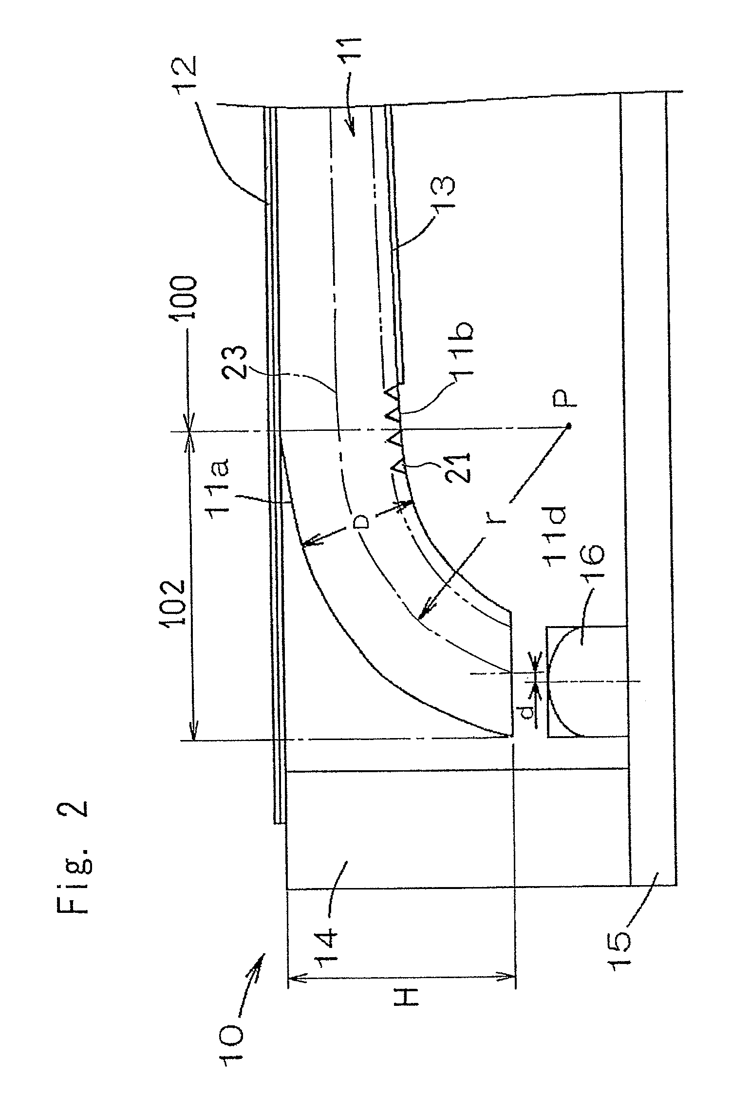
Particularly in the vicinity of a bent portion of the light guide plate, a portion of light propagating within the light guide plate involves a component that impinges at an acute angle to leak out of the light guide body as shown by the arrows in FIG. 4b, making it difficult to assure that the rays of light can propagate to the end of the light guide plate.

Method used


Image

  • Planar lighting device
  • Planar lighting device
  • Planar lighting device

Examples


example

Light Guide Plate

[0038]Using “Iupilon HL-4000”, (manufactured and tradenamed by Mitsubishi Engineering-Plastic Corporation of Japan, as a material for the light guide plate body, the material was supplied to an injection molding machine to form the light guide plate of a predetermined shape under conditions of 240° C. in cylinder temperature, 80° C. in mold temperature and 180 ton in mold clamp pressure.

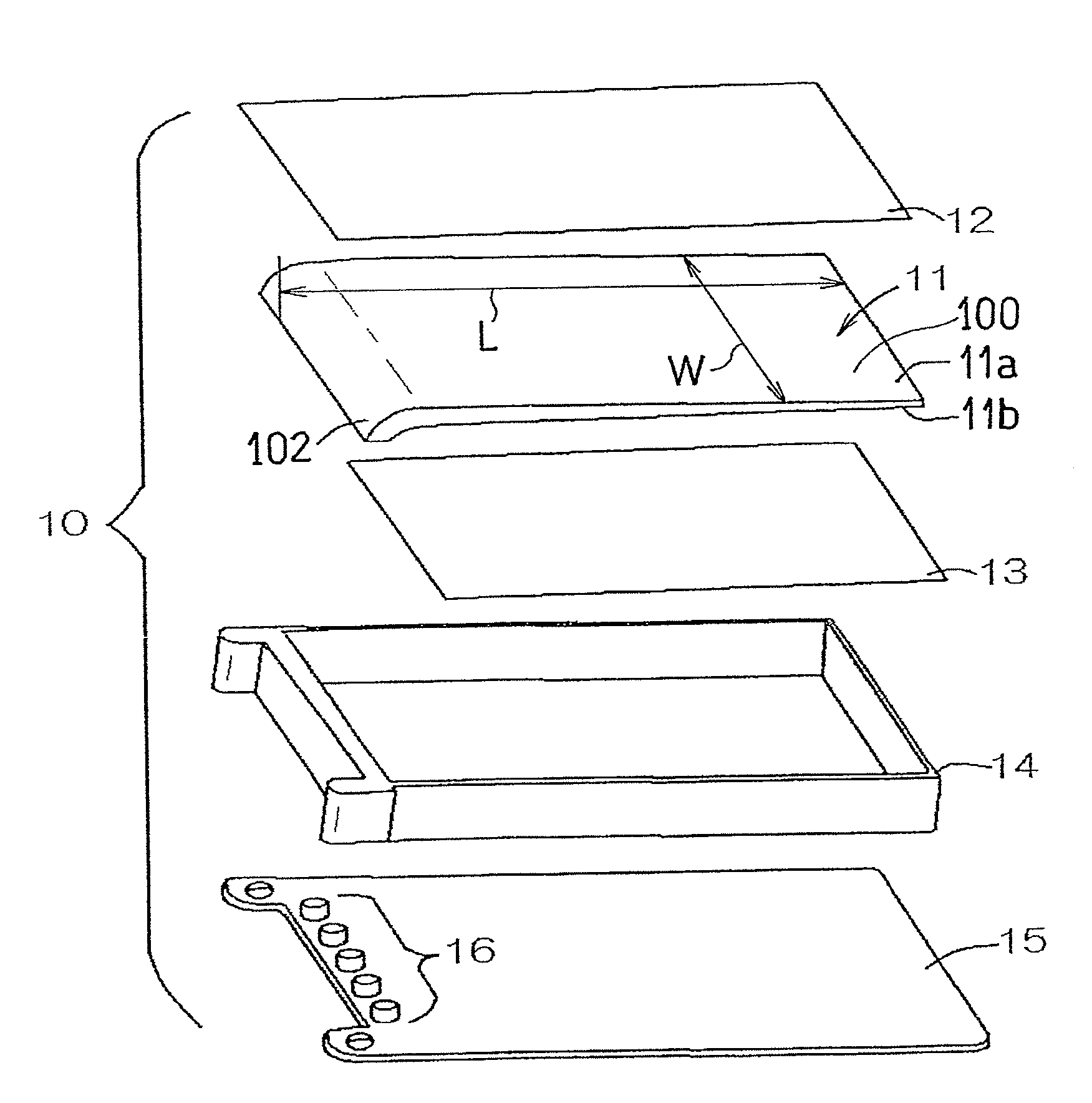
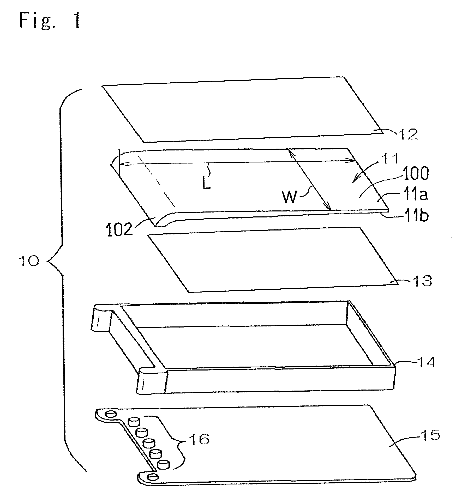
[0039]The light guide plate so manufactured was 55.0 mm in width W and 85.0 mm in length L, representing the wedge shaped sectional shape, when viewed in section taken in a direction lengthwise thereof, with the thickness thereof varying 3.0 mm to 1.0 mm in the lengthwise direction, in which one side or a thick side of the thickness (the surface to surface distance D) was curved towards the rear surface side to define the curvedly descending portion.

[0040]Samples having the respective curvedly descending portions of the radius of curvature varying by 1.0 mm within the range of 3.0 to...


PUM


Abstract

A light guide plate has a light guide plate body and at one side thereof a curvedly descending portion formed by curving front and rear surfaces of the light guide plate, with the surface to surface distance kept uniform, to a coaxial arcuate configuration so as to extend towards a direction of a rear surface of the light guide plate body. Spot light sources disposed in face to face relation with a free end face of the curvedly descending portion are arranged to be displaced towards the front surface of the light guide plate from a mid-center plane between the front and rear surfaces of the curvedly descending portion.

Description

CROSS REFERENCE TO THE RELATED APPLICATION[0001]This application is based on and claims Convention priority to Japanese patent application No. 2011-197632, filed Aug. 25, 2011, the entire disclosure of which is herein incorporated by reference as a part of this application.BACKGROUND OF THE INVENTION[0002]1. Field of the Invention[0003]The present invention relates to a planar lighting device of a kind having a light source disposed in a side edge of a light guide plate.[0004]2. Description of Related Art[0005]Planar lighting devices for providing a planar illumination have hitherto been made available in the market, of a structure, in which rays of light from a light source are introduced into a light guide plate of a flat plate configuration, having a predetermined surface area, and an object to be lighted such as, for example, a liquid crystal display device is illuminated in plane from rear. Of those planar lighting devices, a planar lighting device of a down lighting system, in...

Claims


Application Information

Patent Timeline
Patent Type & Authority Patents(United States)
IPC IPC(8): F21V7/04
CPCG02B6/0046G02B6/0091G02B6/0088G02B6/002
Inventor MIZUNO, HIROSHIAOKI, MOTOHIRO
Owner HAYASHI TELEMPU CO LTD
Learn More