Dual-mode electromechanical variable speed transmission apparatus and method of control

a technology of electromechanical variable and transmission apparatus, which is applied in the direction of electric propulsion mounting, transportation and packaging, gearing, etc., can solve the problems of reducing power transmission efficiency and constraining the effective operating speed ratio of transmission, so as to reduce the power demands of electric machines, reduce manufacturing costs, and simple and compact structure

Inactive Publication Date: 2014-05-27
SHANDONG LIANCHENG GREENMAX TECH
View PDF13 Cites 79 Cited by
  • Summary
  • Abstract
  • Description
  • Claims
  • Application Information

AI Technical Summary

Benefits of technology

[0005]One of the objectives of the current invention is to overcome the aforementioned drawbacks of prior art by providing a novel family of dual-mode electro-mechanical variable speed transmissions that share the common design feature and performance characteristics. These transmissions can operate under at least two different power splitting modes, offering higher power transmission efficiency by avoiding internal power circulation. These transmissions are capable of providing continuously variable output shaft to input shaft speed ratio and independent power regulation in a wide range. They significantly extend the operational speed ratio range.
[0013]Above mentioned technical solution has following benefits: it offers a novel dual-mode electro-mechanical variable speed transmission with reduced power demands on electric machines. Said transmission has simple and compact structure and low manufacturing cost. It is capable of providing continuous operation from reverse to stop to forward, without requiring the conventional launching device. Said transmission significantly improves the overall efficiency of the vehicle.

Problems solved by technology

One of the power paths sees more power than the power transmitted through the transmission, which reduces power transmission efficiency.
This, to a large extent, constrains the effective operating speed ratio of the transmission.

Method used


Image

  • Dual-mode electromechanical variable speed transmission apparatus and method of control
  • Dual-mode electromechanical variable speed transmission apparatus and method of control
  • Dual-mode electromechanical variable speed transmission apparatus and method of control

Examples


embodiment 1

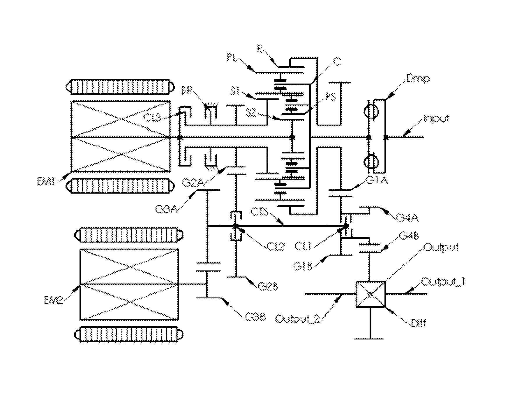
[0029]In embodiment 1, the rotor of the first electric machine EM1 is directly coupled to sun gear S, establishing a fixed connection with the first branch (I) of the three-branch gear system with a fixed speed ratio of 1. The input shaft (Input) couples to the planet carrier C via a torsion damper or a shack load absorber (Dmp), establishing a connection with the second branch (II) of the three-branch gear system with a fixed speed ratio of 1. The output shaft system (Output) couples to ring gear R via two pairs of gears G1A and G1B, and G4A and G4B, establishing a connection with the third branch (III) of the three-branch gear system with a speed ratio of GR1×GR4. The second electric machine EM2, couples either to the ring gear R through gears G1A and G1B, and gears G3A and G3B, establishing a first selective connection to the third branch of the three-branch gear system with a speed ratio of GR1×GR3, or to the planet carrier C through gears G2A and G2B, and gears G3A and G3B, est...

embodiment 2

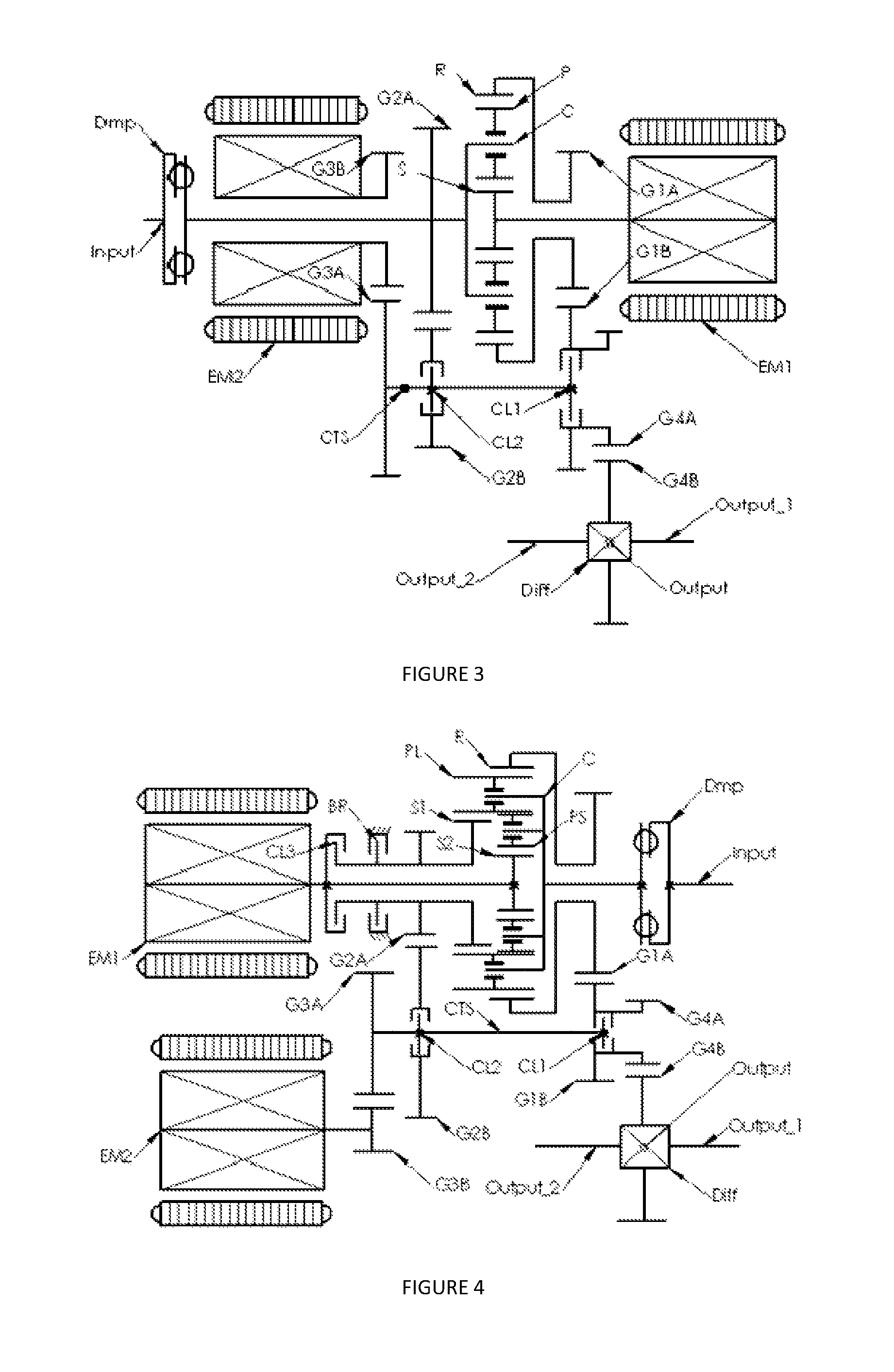
[0047]FIG. 4 shows embodiment 2 of the current invention. It represents a typical example of the second type of embodiments. The transmission shown in FIG. 4 is comprised of a four-branch planetary gear system, an input shaft (Input), a counter shaft (CTS), an output shaft system (Output), a first clutch CL1, a second clutch CL2, a first electric machine EM1 and a second electric machine EM2 along with the electric drives (CTRL, not shown) for the electric machines. The four-branch planetary gear system is constituted by a Ravigneaux planetary gear-train. It contains a large sun gear S1, a small sun gear S2, a set of long planet gears PL, a set of short planet gears PS, a ring gear R and a planet carrier C. Each of the long planet gears PL is in internal meshing engagement with the ring gear R and in external meshing engagement with the large sun gear S1; each of the short planet gears PS is in external meshing engagement with a corresponding long planet gear PL and with the small s...

embodiment 3

[0091]The rotor of the first electric machine EM1 couples directly to the first ring gear R1, establishing a fixed connection to the first branch of the four-branch gear system with a fixed speed ratio of 1. The output shaft system (Output) couples to the second ring gear R2 through gear sets G1A and G1B, and G4A and G4B, establishing a connection to the second branch of the four-branch gear system with a speed ratio of GR1×GR4. Input shaft (Input) couples through a torsion damper (Dmp) to the planet carrier C, establishing a connection to the third branch of the four-branch gear system with a fixed speed ratio of 1. The second electric machine EM2 selectively couples either to the second ring gear R2 through gear set G1A and G1B, establishing a first selective connection to the second branch with a first speed ratio of GR1, or to the sun gear S through gear set G2A and G213, establishing a second selective connection to the fourth branch of the four-branch gear system with a second...


PUM


Abstract

A dual-mode electro-mechanical variable speed transmission includes an input shaft, an output shaft system, a gear system having at least three branches, two electric machines, and at least a clutch. The first electric machine couples to a branch of the gear system, the output shaft system couples to another branch of the gear system, the input shaft couples to the remaining branch or one of the remaining branches of the gear system, and the second electric machine selectively couples either to the same branch that is coupled to the output shaft system with a speed ratio or to one of the remaining branches that that is not coupled to the first electric machine with a different speed ratio. The transmission provides at least two power splitting modes to cover different speed ratio regimes. The transmission can also provide at least a fixed output shaft to input shaft speed ratio.

Description

CROSS-REFERENCE TO RELATED APPLICATIONS[0001]This application is a National Phase Application of PCT International Application No. PCT / CN2008 / 001945, International Filing Date Nov. 28, 2008, claiming priority of Chinese Patent Application 200710195199.8, filed Dec. 4, 2007, both of which are incorporated by reference herein.FIELD OF THE INVENTION[0002]The invention is related to a dual mode electro-mechanical variable speed transmission. It can be used in a wide variety of vehicle applications and power equipment.BACKGROUND OF THE INVENTION[0003]An internal combustion engine operates in a certain range of speed and power. Inside this range, there usually exists a smaller regime where the engine achieves optimal performance. On the other hand, driving conditions vary enormously, not only in wheel speed but also in driving torque at the drive wheels. A combination of a given speed and torque defines a power state. Matching the power state of the engine with that of the drive wheels is...

Claims


Application Information

Patent Timeline
Patent Type & Authority Patents(United States)
IPC IPC(8): F16H3/72F16H37/06B60K6/445B60K6/20F16H48/06
CPCF16H2200/2097B60K6/445F16H2200/2007B60K6/547B60K6/365B60W10/02F16H2200/2035F16H2037/0873F16H2200/2005F16H2037/104B60W10/11B60W10/08F16H2037/103F16H3/728Y02T10/6239F16H2037/101F16H2200/0034B60K1/02Y10T477/23Y10T477/26Y02T10/62
Inventor AI, XIAOLINXUE, RUIXUE, ZHONGHEAI, XIAOZHI
Owner SHANDONG LIANCHENG GREENMAX TECH
Why Eureka
Try Eureka