Eureka AIR delivers breakthrough ideas for toughest innovation challenges, trusted by R&D personnel around the world.

Kneading extruder

a technology of extruder and kneading, which is applied in the direction of dough shaping, manufacturing tools, applications, etc., can solve the problems of affecting the quality of products, the physical property of the extruded material extruded from the die, and the inability to avoid change in the physical property of the kneaded material, so as to achieve the effect of compatibility of the kneading property and the stabilization of the knead

Active Publication Date: 2014-05-13
SAWA CORP
View PDF22 Cites 0 Cited by
  • Summary
  • Abstract
  • Description
  • Claims
  • Application Information

AI Technical Summary

Benefits of technology

The invention is a kneading extruder that can mix different types of raw materials. The extruder has a device that pushes out the material that has been mixed. This device makes sure that the pressure of the material remains constant as it is pushed out. This allows for a steady supply of material, while keeping the amount of raw materials and the amount of rotation of the screw shafts constant. This results in a constant and stable mixing of the materials.

Problems solved by technology

Variability in the number of rotations of the screw shafts 511 in addition to variation in the supplying quantity of the raw materials causes change in the rate of screw shear that is important among conditions of kneading and thus makes it impossible to avoid change in physical property of the kneaded material.
In the conventional kneading extruder 501, accordingly, the physical property of the extruded material extruded from the die 516 is unstable and there is a fear that unstability in molded state may exert an influence on quality of products, depending upon combination of the supplied raw materials, form of the end product and / or the like.
In particular, there is a fear that such an influence may arise more conspicuously on condition that the molding is carried out with use of the kneading extruder in small size having a comparatively small extrusion quantity.
In the kneading extruder in which films, tubes, or the like are directly molded with use of extruded material therefrom, state of molded bodies is unstable because the kneading property of the extruded material directly influences conditions of the molded bodies.
On condition that two or more types of the raw materials having different specific gravities are mixed, it is still difficult to stabilize the kneading property.

Method used


Image

  • Kneading extruder
  • Kneading extruder
  • Kneading extruder

Examples


first embodiment

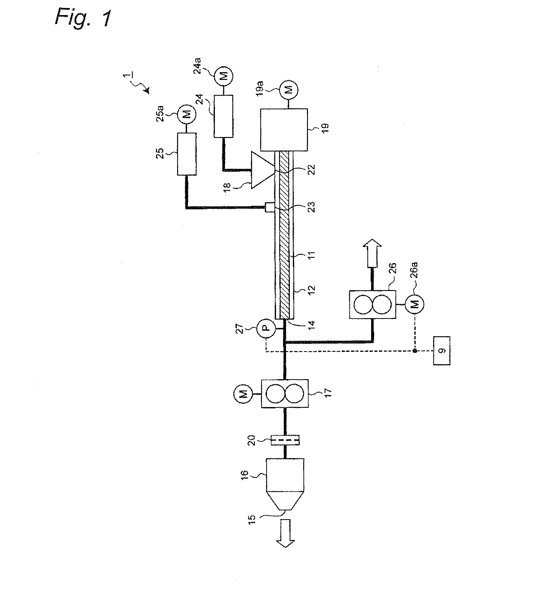
[0044]FIG. 1 shows a schematic representation illustrating general configuration of a kneading extruder 1 in accordance with a first embodiment of the invention. As shown in FIG. 1, the kneading extruder 1 has a screw shaft 11, e.g., having a single shaft structure, a barrel 12 in which the screw shaft 11 is rotatably placed in an inside space thereof, raw material supplying devices for supplying raw materials into a space between the barrel 12 and the screw shaft 11, a die 16 that is in communication with a barrel extrusion port 14 which is an outlet of the barrel 12 for kneaded material and that extrudes the kneaded material supplied from the barrel 12 to outside of the kneading extruder, and a booster pump 17 that is provided between the barrel 12 and the die 16 and that supplies the kneaded material extruded from the barrel extrusion port 14 to the die 16 while boosting pressure of the kneaded material.

[0045]A first raw material supply port 22 through which first raw material is...

second embodiment

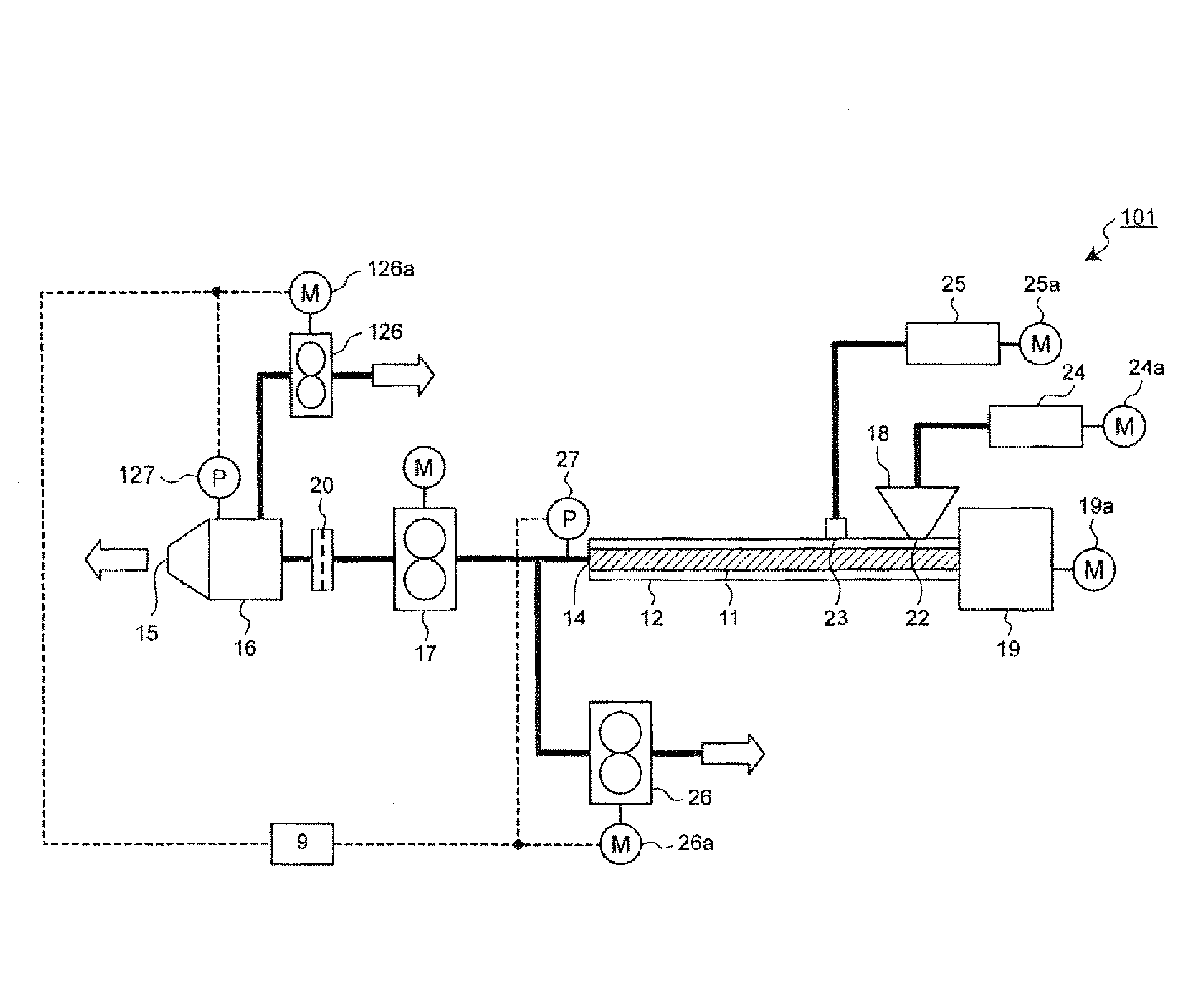
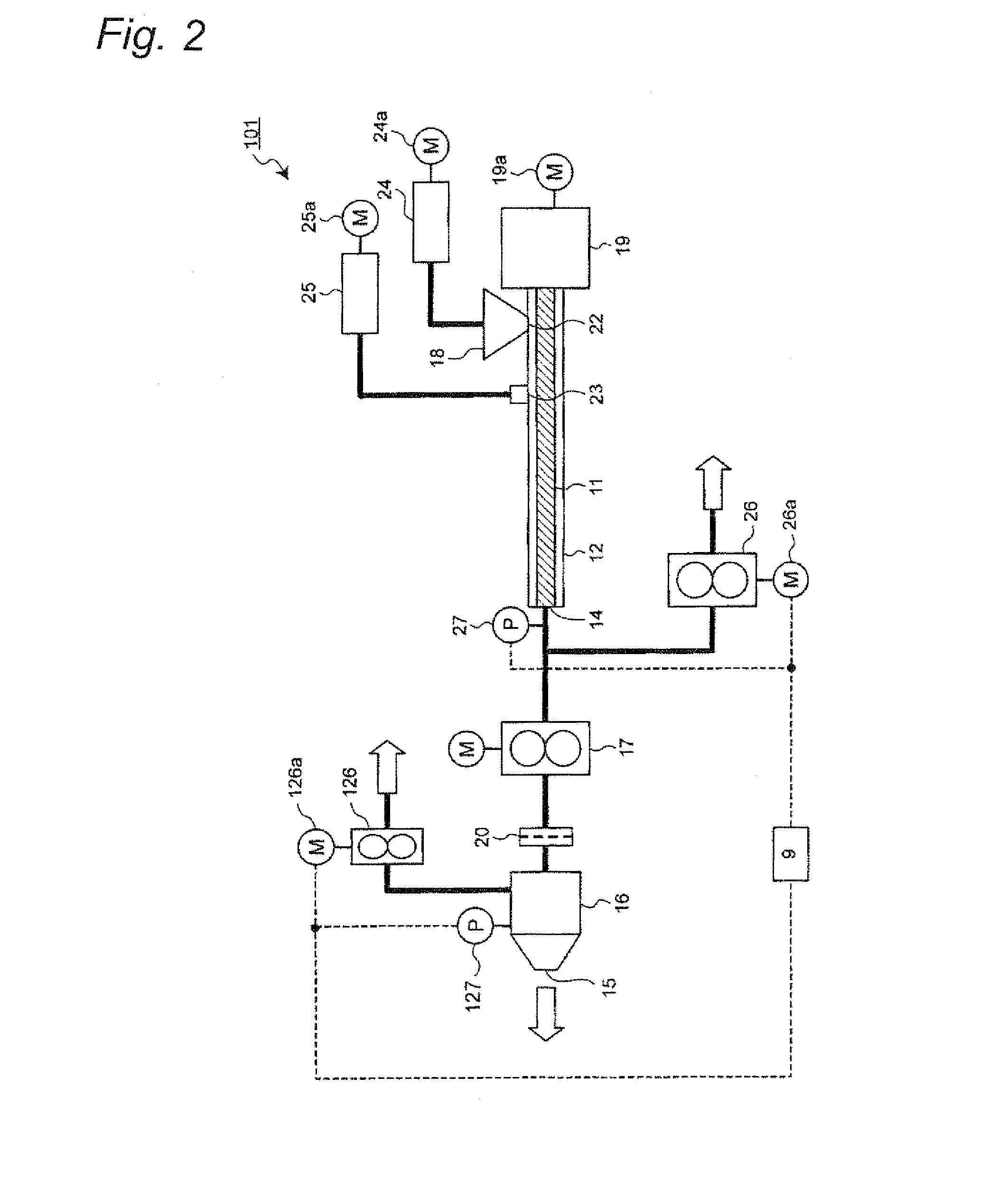
[0071]The invention is not limited to the first embodiment and can be embodied in other various manners. For instance, FIG. 2 shows a schematic representation illustrating general configuration of a kneading extruder 101 in accordance with a second embodiment of the invention. For the kneading extruder 101 of FIG. 2, the same components as those of the kneading extruder 1 of the first embodiment are designated by the same reference characters and description thereof is omitted.

[0072]As shown in FIG. 2, the kneading extruder 101 of the second embodiment is different from the configuration of the first embodiment in that the device 101 has a configuration for ejecting a portion of kneaded material in the die 16. Hereinbelow, only different components will be described.

[0073]As shown in FIG. 2, a second ejection pump 126 is connected through a pipeline to the die 16. The second ejection pump 126 has a drive motor 126a of which the number of rotations can variably be controlled. A secon...

third embodiment

[0076]FIG. 3 shows a schematic representation illustrating a general configuration of a kneading extruder 201 in accordance with a third embodiment of the invention. For the kneading extruder 201 of FIG. 3, the same components thereof as those of the kneading extruder 1 of the first embodiment are designated by the same reference characters and description thereof is omitted.

[0077]As shown in FIG. 3, the kneading extruder 201 of the third embodiment is different from the configuration of the first embodiment in that screw shafts 11 have double shaft structure, in that a supplying device for third raw material is added as the raw material supplying device, and in that a plurality of systems each extending from a booster pump 17 to a die 16 are provided. Hereinbelow, only different components will be described.

[0078]As shown in FIG. 3, a third raw material supply port 221 is additionally provided on a barrel 212, so that the third raw material different in type from the first and seco...


PUM

PropertyMeasurementUnit
constant speedaaaaaaaaaa
pressureaaaaaaaaaa
pressure detectionaaaaaaaaaa

Abstract

A kneading extruder includes a barrel having an extrusion port through which kneaded material including first and second liquid raw material is extruded, and a screw shaft placed in the barrel, the screw shaft kneading the first and second raw material to produce the kneaded material in melted state. A screw driving device continuously rotates the screw shaft at a constant speed, and a die communicates with the extrusion port of the barrel, the die having an extrusion port through which the kneaded material in a pressurized state is extruded. An ejection device ejects a portion of the kneaded material between the extrusion port of the barrel and the extrusion port of the die, the ejection device including an ejection quantity regulating unit for regulating the ejection quantity of the kneaded material so that the pressure of the kneaded material at the extrusion port of the barrel is kept constant.

Description

TECHNICAL FIELD[0001]The present invention relates to a kneading extruder that kneads a plurality of types of raw materials to produce kneaded material in melted state and that extrudes the produced kneaded material, by rotation of screw shafts.BACKGROUND ART[0002]A kneading extruder 501 as shown in FIG. 5 has conventionally been known, for instance, as a kneading extruder that kneads a plurality of types of raw materials to produce kneaded material and that extrudes the kneaded material (see Patent Document 1, for instance).[0003]As shown in FIG. 5, the conventional kneading extruder 501 includes a screw shaft 511 or screw shafts 511 having a single-shaft structure or double-shaft structure, a barrel 512 in which the screw shaft(s) is rotatably placed in an inside space thereof, a raw material feeder 513 for supplying the raw materials into a space between the barrel 512 and the screw shaft(s) 511, a die 516 that is in communication with a barrel extrusion port 514 which is an outl...

Claims


Application Information

Patent Timeline
Patent Type & Authority Patents(United States)
IPC IPC(8): B29C47/92B29C48/255B29C48/395B29C48/40B29C48/72B29C48/92
CPCB29C47/40B29C2947/92876B29C47/1081B29B7/728B29C2947/92514B29B7/726B29C47/92B29B7/606B29C2947/92828B29C47/0811B29C47/8815B29C47/38B29C2947/926B29C47/369B29C47/6056B29C47/364B29C47/1009B29C47/362B29B7/603B29C2947/9259B29C47/385B29C47/0014B29B7/38B29B9/065B29C47/68B29C2947/92885B29C2947/92904B29C48/397B29C48/92B29C48/05B29C2948/92876B29C48/297B29C48/08B29C48/09B29C48/286B29C48/362B29C48/37B29C48/39B29C48/395B29C48/40B29C48/57B29C48/67B29C48/69B29C48/911B29C48/919B29C2948/92514B29C2948/9259B29C2948/926B29C2948/92828B29C2948/92885B29C2948/92904B29C48/255B29B7/72B29C48/00
Inventor SAWA
Owner SAWA CORP
Why Eureka
Eureka Blog
Learn More