
Separator including porous coating layer and electrochemical device including the same

a technology of electrochemical device and porous coating layer, which is applied in the direction of electrical equipment, cell components, batteries, etc., can solve the problems of disadvantageous fabrication complexity, thermal runaway, safety problems of lithium ion batteries, etc., and achieve low melting point, reduce the area of pores, and improve the conductivity of ptc particles

Active Publication Date: 2014-04-22
TORAY BATTERY SEPARATOR FILM +1
View PDF22 Cites 0 Cited by
  • Summary
  • Abstract
  • Description
  • Claims
  • Application Information

AI Technical Summary

Benefits of technology

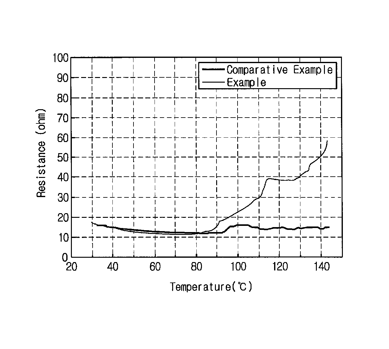
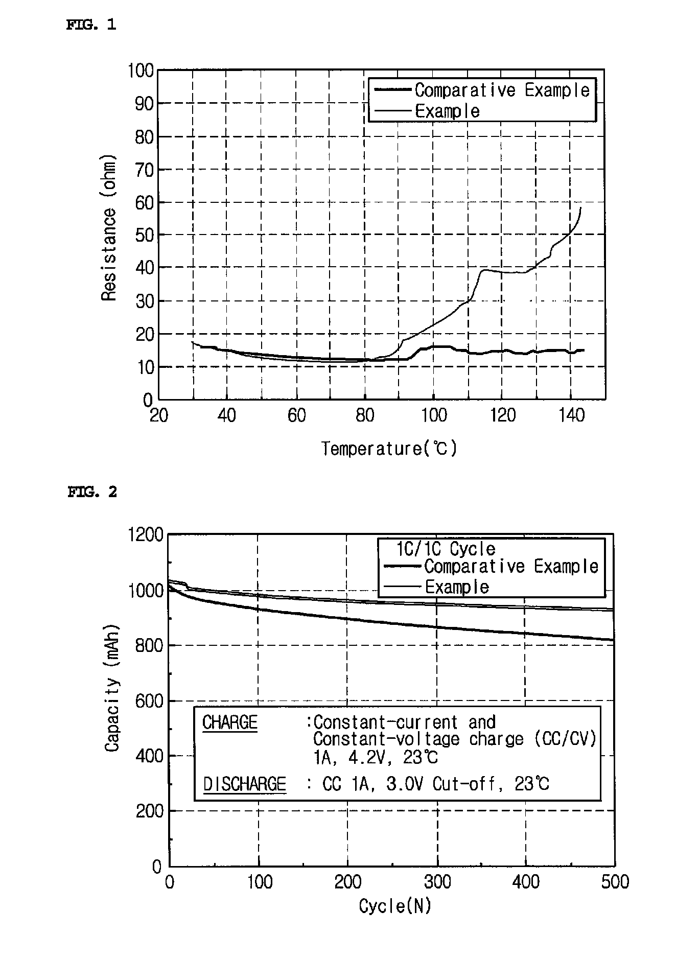
The present invention is a separator used in high-capacity electrochemical devices. It has a porous coating layer made of conductive particles and a low melting point resin. When the device overheats or reaches thermal runaway, the resin expands and reduces the area of the pores, improving safety and stability. The inorganic particles in the filler particles also prevent short circuits and damage to the device. Overall, this separator offers improved safety and stability for electrochemical devices.

Problems solved by technology

However, such lithium ion batteries suffer from safety problems, such as fire or explosion, encountered with the use of organic electrolytes and are disadvantageously complicated to fabricate.
Overheating of an electrochemical device may cause thermal runaway or puncture of a separator may pose an increased risk of explosion.
This thermal shrinkage behavior may cause short circuits between a cathode and an anode.
The insulating porous coating layers formed on the porous substrates contribute to an improvement in the stability of electrochemical devices but inevitably bring about an increase in the thickness of the separators, making it difficult to fabricate high-capacity batteries.

Method used


Image

  • Separator including porous coating layer and electrochemical device including the same
  • Separator including porous coating layer and electrochemical device including the same
  • Separator including porous coating layer and electrochemical device including the same

Examples


example 1

[0055]Production of Separator

[0056]Polyvinylidene fluoride-co-trifluorochloroethylene (PVdF-CTFE) and cyanoethylpullulan were added in a weight ratio of 10:2 to acetone. The mixture was dissolved at 50° C. for at least about 12 hr to prepare a binder polymer solution.

[0057]Polyethylene and carbon black particles (1:1, w / w) were homogenized to prepare conductive PTC particles having an average particle diameter of 400 nm.

[0058]The conductive PTC particles were mixed with BaTiO3 powder in a weight ratio of 1:9 to prepare filler particles. The filler particles were dispersed in the binder polymer solution to prepare a slurry. The weight ratio of the filler particles to the binder polymer solution was adjusted to 90:10. The slurry was dip-coated on a 12 μm thick polyethylene terephthalate non-woven fabric to form a porous coating layer. The non-woven fabric was composed of microfibers having an average thickness of about 3 μm and had a pore size distribution in which more than 50% of th...


PUM

PropertyMeasurementUnit
particle diameteraaaaaaaaaa
melting pointaaaaaaaaaa
diameteraaaaaaaaaa

Abstract

Disclosed is a separator. The separator includes a planar non-woven fabric substrate having a plurality of pores, and a porous coating layer formed on at least one surface of the non-woven fabric substrate. The porous coating layer is composed of a mixture of filler particles and a binder polymer. The filler particles include conductive positive temperature coefficient (PTC) particles composed of a mixture of conductive particles and a low melting point resin having a melting point lower than that of the non-woven fabric substrate. Due to the presence of the conductive PTC particles, the porous coating layer can be imparted with a shutdown function against thermal runaway. In addition, the porous coating layer exhibits appropriate electrical conductivity. Therefore, the separator is suitable for use in a high-capacity electrochemical device.

Description

CROSS-REFERENCE TO RELATED APPLICATIONS[0001]The present application is a continuation application of International Application No. PCT / KR2009 / 007505, filed Dec. 15, 2009, published in Korean, which claims priority under 35 U.S.C.§119(a) to Korean Patent Application Nos. 10-2008-0136592 and 10-2009-0123873 filed at the Korean Intellectual Property Office on Dec. 30, 2008 and Dec. 14, 2009, respectively, the entire contents of which are incorporated herein by reference.TECHNICAL FIELD[0002]The present invention relates to a separator for an electrochemical device, such as a lithium secondary battery, and an electrochemical device including the separator. More specifically, the present invention relates to a separator in which a porous coating layer composed of a mixture of filler particles and a binder polymer is formed on at least one surface of a non-woven fabric substrate and an electrochemical device including the separator.BACKGROUND ART OF THE INVENTION[0003]Recently, there has...

Claims


Application Information

Patent Timeline
Patent Type & Authority Patents(United States)
IPC IPC(8): H01M2/16H01M50/417H01M50/42H01M50/426H01M50/429H01M50/454H01M50/457H01M50/491
CPCH01M10/4235H01M2200/106H01M2/162Y02E60/12H01M2/1666H01M2/1686Y02E60/10H01M50/44H01M50/417H01M50/429H01M50/457H01M50/454H01M50/491H01M50/426H01M50/42H01M10/0525H01M50/451H01M50/446H01M50/431H01M50/443H01M50/489
Inventor PARK, PIL-KYUKIM, JONG-HUNAHN, SOON-HOKIM, JE-YOUNG
Owner TORAY BATTERY SEPARATOR FILM
Learn More