Oil sand production without CO2 emission

a technology of oil sand and co2 emission, which is applied in the direction of machines/engines, heat recovery, borehole/well accessories, etc., can solve the problems of high co2 /sub>emission, relatively high cost, and negative environmental effects of oil sand production

Active Publication Date: 2014-04-22
CO2 CAPSOL
View PDF19 Cites 4 Cited by
  • Summary
  • Abstract
  • Description
  • Claims
  • Application Information

AI Technical Summary

Problems solved by technology

Oil sand is a resource that has been exploited for some time but exploitation of this resource has negative environmental aspects in addition to be relatively expensive.
Recovering, processing and upgrading of the mixture to obtain commercial oil are energy demanding and result in high CO2 emission.
This has caused environmental concerns related to this exploitation.
The toe to heel method is hard to control and is not suitable for all formations.
The methods for heating the formation are all energy consuming methods, where natural gas, oil and / or coal are combusted to produce steam and / or electrical power, an activity that causes CO2 emission from the production of oil at an unacceptable high level.

Method used


Image

  • Oil sand production without CO2 emission
  • Oil sand production without CO2 emission
  • Oil sand production without CO2 emission

Examples


first embodiment

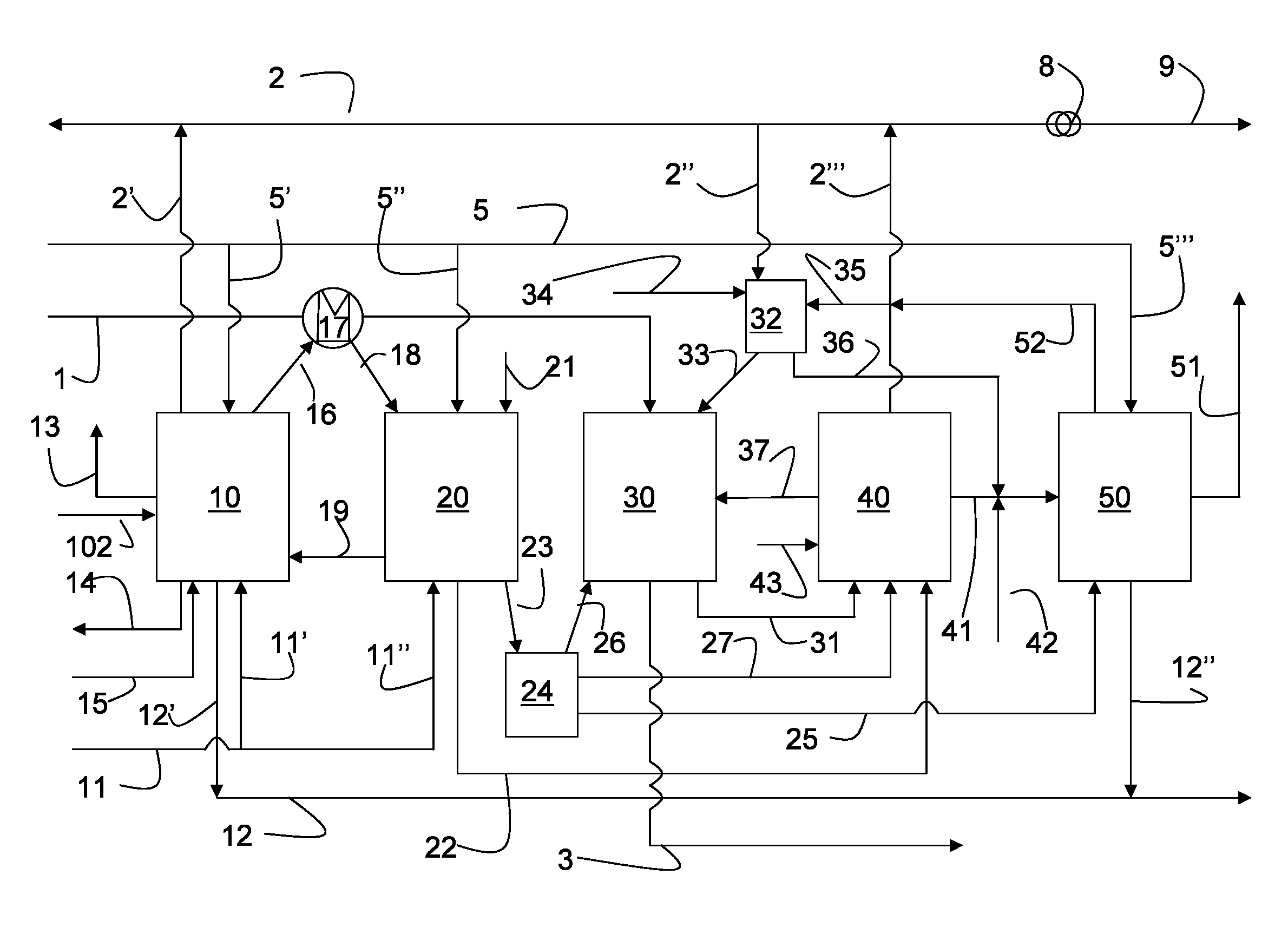
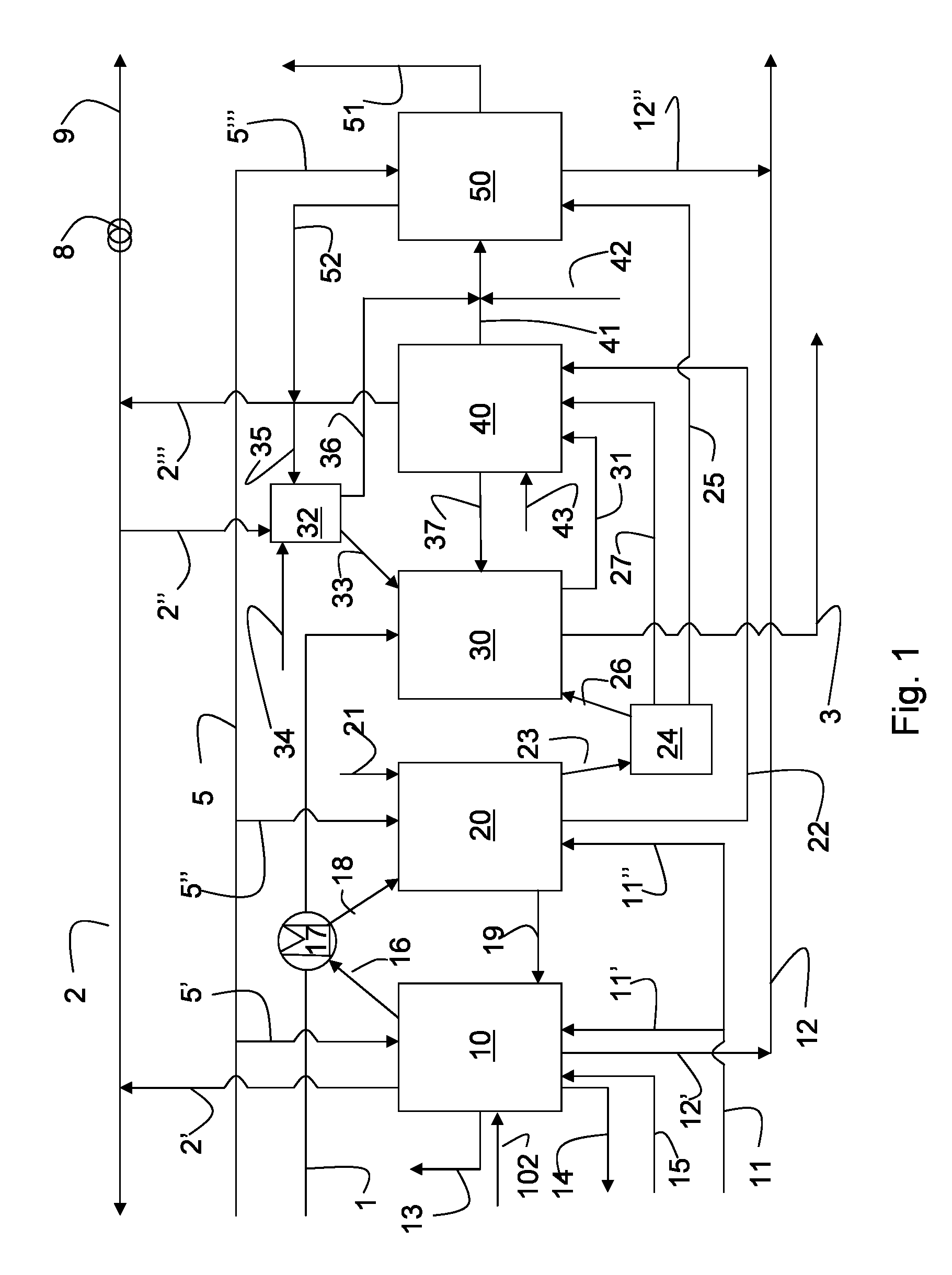
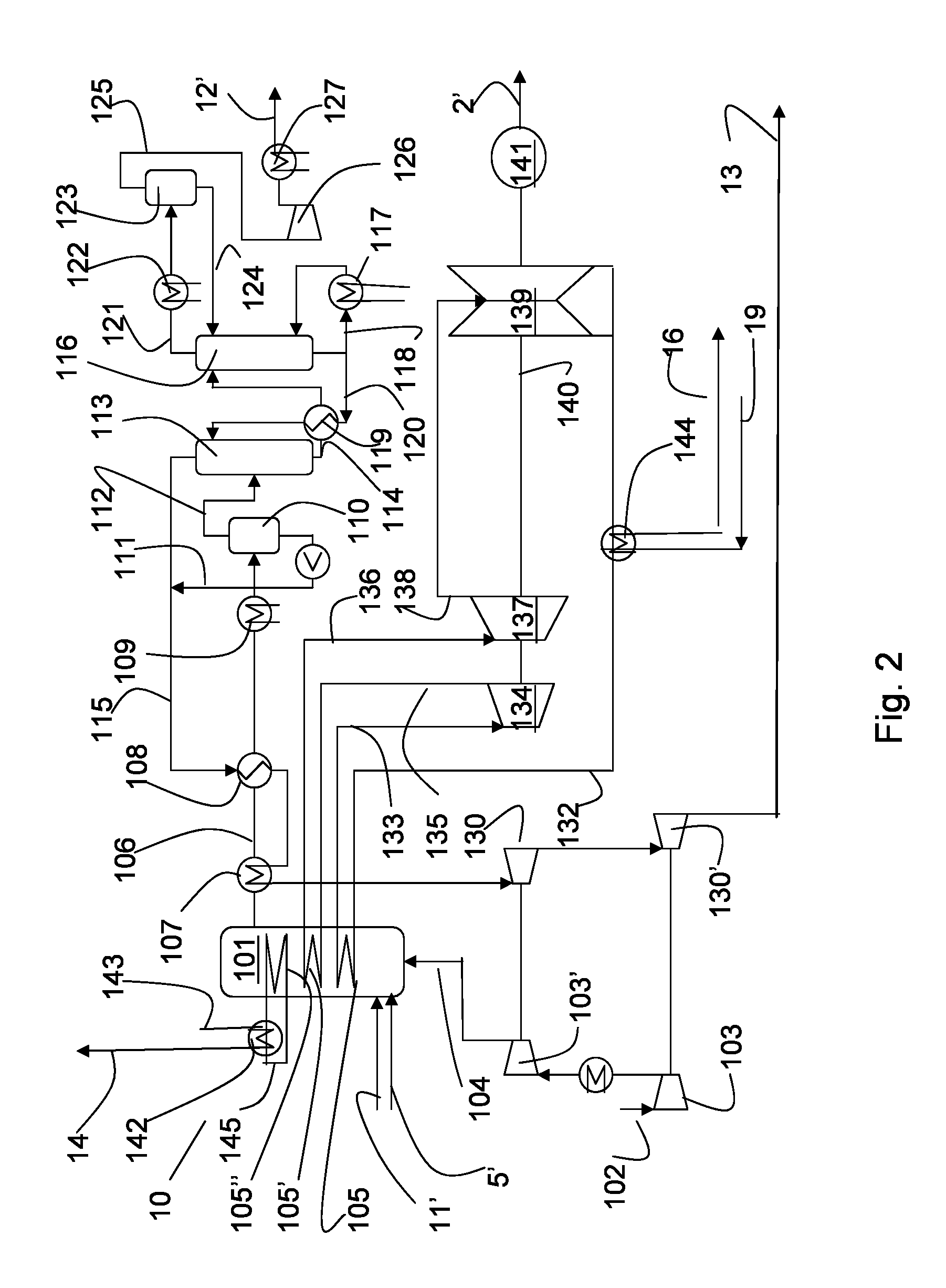
[0051]Depending on the relative requirement for electrical power and steam for EOR, the tube coils 105, 105′ and 105″ may be dimensioned or operated to meet different needs. In a first embodiment illustrated in FIG. 2, steam and superheated steam are produced in tube coils 105, 105′, respectively, which steam is expanded over steam turbines 134, 137, 139 for generation of power as described above. Steam EOR is generated as described above by steam generation in the tube coil 105″ for heating of water and generation of steam in the heat exchanger 142. Steam for EOR is withdrawn through line 14.

second embodiment

[0052]In a second embodiment, illustrated in FIG. 3, tube bundles 105, 105′ are omitted and substituted totally by tube bundle 105″ so that all steam production in the boiler is produced in tube coils 105″ and is used for EOR.

third embodiment

[0053]FIG. 4 illustrates a third embodiment, wherein tube coil 105′ is omitted. Both tube coils 105 and 105″ may be dimensioned individually to cool the combustion gases in the combustion chamber to the required temperature, so that the plant may be operated in different modes, a normal mode where both electrical power and steam for EOR are produced, and alternative modes where all steam generated in the tube coils are produced in either tube coils 105 or 105″, to result in production of electrical power only or steam for EOR only.

[0054]Any electrical power generated by the power plant 10 is withdrawn through lines 2′, 2 to be used in the plant 1 or to be exported. The electrical power in line 2 may be used as a supplement of alternative to steam injection to promote production of bitumen, by means of electrodes inserted into the oil sand field.

[0055]Low temperature heat from the power plant, e.g. from any of the coolers such as a cooler 144 provided in line 132, may be withdrawn th...


PUM


Abstract

A plant for generation of steam for oil sand recovery from carbonaceous fuel with capture of CO2 from the exhaust gas, comprising heat coils (105, 105′, 105″) arranged in a combustion chamber (101) to cool the combustion gases in the combustion chamber to produce steam and superheated steam in the heat coils, steam withdrawal lines (133, 136, 145) for withdrawing steam from the heat coils, an exhaust gas line (106) for withdrawal of exhaust gas from the combustion chamber (101), where the combustion chamber operates at a pressure of 5 to 15 bara, and one or more heat exchanger(s) (107, 108) are provided for cooling of the combustion gas in line (106), a contact device (113) where the cooled combustion gas is brought in countercurrent flow with a lean CO2 absorbent to give a rich absorbent and a CO2 depleted flue gas, withdrawal lines (114, 115) for withdrawal of rich absorbent and CO2 depleted flue gas, respectively, from the contact device, the line (115) for withdrawal of CO2 depleted flue gas being connected to the heat exchangers (107, 108) for heating of the CO2 depleted flue gas, and where the rich absorbent is regenerated an absorbent regenerator (116), the regenerated lean absorbent is recycled to the absorber (113), and a gas withdrawal line (121) connected to the absorber for withdrawal of CO2 and steam from the regenerator (116), is described.

Description

TECHNICAL FIELD[0001]The present invention relates to a method and a plant for oil sand recovery, heavy oil upgrading and power production with significantly reduced CO2 emission compared to the solutions according to the state of the art.BACKGROUND[0002]The global oil demand is increasing at the same time as easily recoverable oil resources become are recovered. Oil sand is a resource that has been exploited for some time but exploitation of this resource has negative environmental aspects in addition to be relatively expensive.[0003]Oil sands, also known as tar sands or extra heavy oil, are a kind of bitumen deposit that is found in a mixture of sand and / or clay, and water. Recovering, processing and upgrading of the mixture to obtain commercial oil are energy demanding and result in high CO2 emission. This has caused environmental concerns related to this exploitation.[0004]Oil sand is recovered either by opencast mining, or by drilling into an oil and field and withdrawing the b...

Claims


Application Information

Patent Timeline
Patent Type & Authority Patents(United States)
IPC IPC(8): E21B43/24
CPCE21B43/36F23J15/02Y02E20/346F02C3/20F23J15/08H02K7/18E21B43/24F23J2219/60F23J15/06Y02E20/363Y02C10/04Y02C10/06Y02E20/12F22B37/008F02C6/18Y02E20/18F23J2215/50F23J15/006F01K23/067F01K17/04Y02E20/30Y02E20/32
Inventor BORSETH, KNUTCHRISTENSEN, TORFLEISCHER, HENRIK
Owner CO2 CAPSOL
Why Eureka
Try Eureka