
Tunable optical filter and spectrometer

a spectrometer and optical filter technology, applied in the field of optical filters, can solve the problems of poor response time, large volume and cost of traditional spectrometers, and limited response time of network control loops, and achieve high fidelity of measured spectra, fast speed, and high precision

Active Publication Date: 2014-04-15
LUMENTUM OPERATIONS LLC
View PDF13 Cites 7 Cited by
  • Summary
  • Abstract
  • Description
  • Claims
  • Application Information

AI Technical Summary

Benefits of technology

[0016]A tunable optical filter of the present invention is capable of operating at high precision and a fast speed, while being scalable to multiple input and output port counts. High fidelity of measured spectra is achieved by using scanning of optical beams. Advantageously, both input and output optical beams are synchronously scanned by the same scanner to improve the wavelength scanning range and / or reduce the required scanning distance or scanning angle. The optical configuration of a tunable filter of the present invention allows scalability by providing multiple signal paths. Furthermore, using arrays of egress optical ports allows one to further reduce the required range of mechanical scanning while improving the light collection efficiency, speed of operation, and reliability. Advantageously, multi-row fiber arrays can be used to ease optical alignment and provide a compact multi-path tunable optical filter that can be used for optical channel monitoring (OCM) applications.
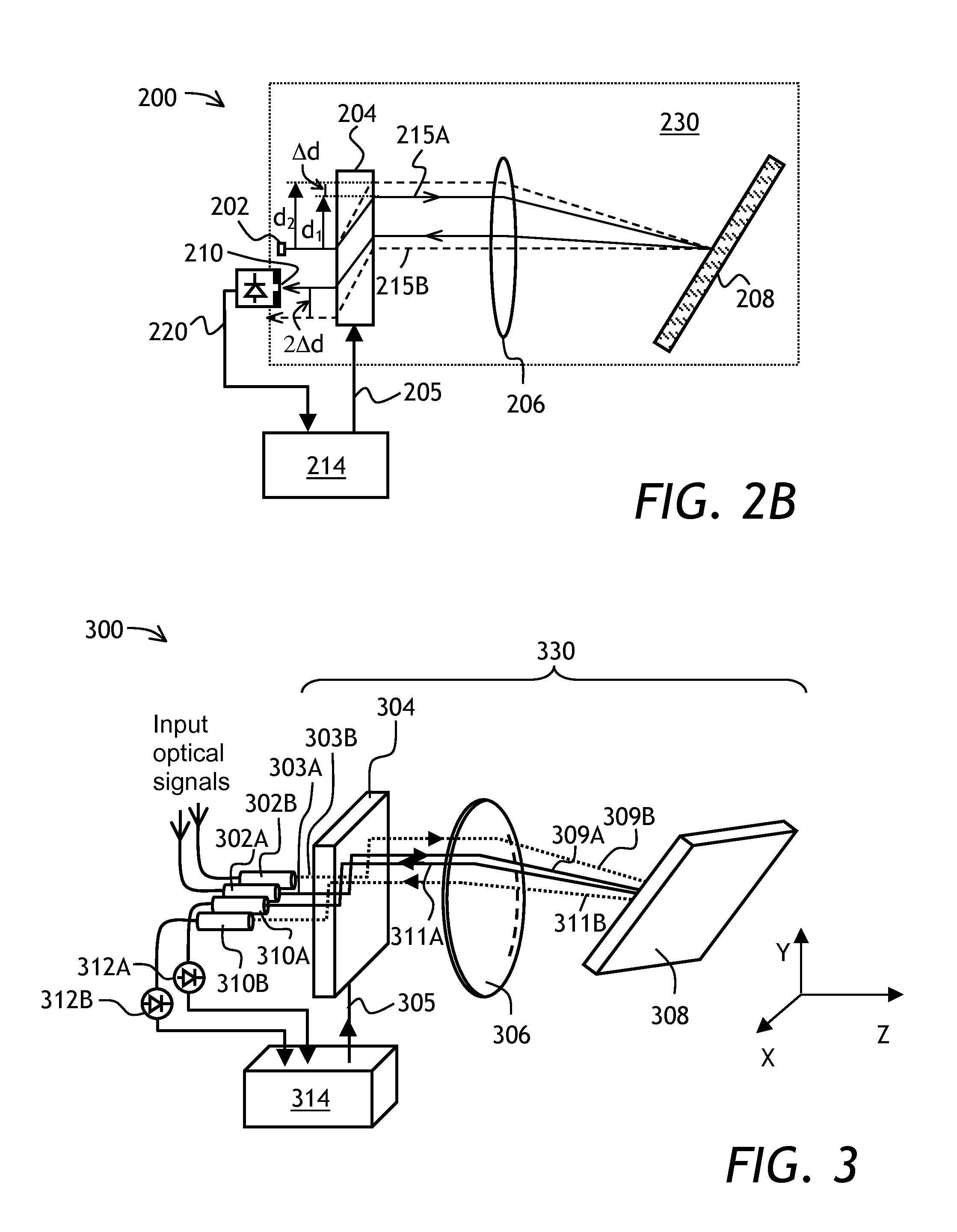
[0026]In one embodiment, the tunable optical filter can have a plurality of input ports and a plurality of arrays of egress ports, so that each optical path of the N optical paths is now associated with the M egress ports. In other words, each output port, corresponding to a particular input port of the N input ports, is now an egress port of a particular array of N arrays of M egress ports. Thus, the multipath property of the tunable filter can be combined with the increased speed due to reduced scanning range of the beam translator. In this embodiment, the egress ports of each array are disposed in a single plane. In operation, the reflected dispersed optical beams are translated by the beam translator in the corresponding planes of the arrays of the egress ports, so that each dispersed optical beam is translated across each egress port of one of the arrays of the egress ports, thereby tuning the central wavelength at each egress port. The central wavelengths at different egress ports of a same one of the arrays of the egress ports are shifted with respect to each other, while the central wavelengths of the individual optical filter paths are tuned synchronously.
[0027]In any of the above described embodiments of the tunable filter, the linear translator preferably includes a tiltable mirror, such a micro-electromechanical (MEMS) mirror, coupled to an angle-to-offset converting element such as a lens. Further, the element having optical power can be made in a form of a single concave mirror, resulting in a very compact yet efficient device. Waveguide arrays can be used for ease of alignment of the multiple input, output, and / or egress ports.

Problems solved by technology

Traditional spectrometers are generally bulky and costly.
Network control loops are thus limited in their response, at least in part, by the rate at which the OCM can update the optical power measurement.
However, this approach suffers from poorer response time as the aggregate time to monitor all N points is equal to
However, this approach suffers from aforementioned cost and size disadvantages of deploying multiple OCM.
In this case, in addition to the considerably slower measurement time, the measurement at input and output ports are no longer made at the same time.
To the extent that the power levels being measured are not strictly constant over time, there is some confounding imperfect measurement of the inferred WSS attenuation.
Disadvantageously, the number of photodiodes in the photodiode array scales proportionally to the number of wavelength channels and spectral resolution, thereby increasing the size and cost of the device and reducing its reliability.
However, these arrays are expensive.
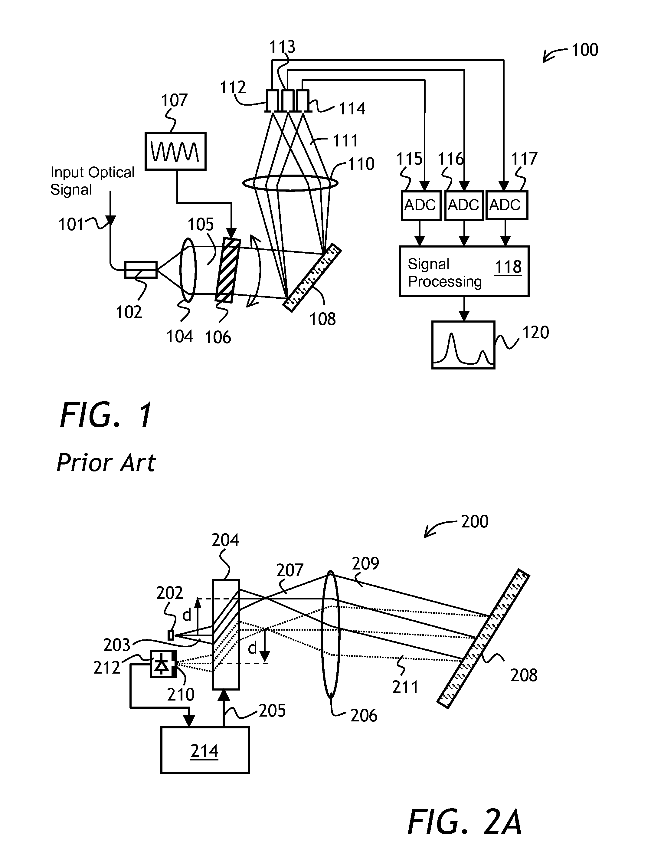
One disadvantage of the spectrometer 100 is a reduced reliability, limited scanning range, and high cost.
Another is large size, which is detrimental in OCM applications.
Yet another disadvantage, which is common to all prior-art spectrometers disclosed above, is that it only has a single optical signal path.
Thus, when multiple optical signals need to be measured, multiple OCM have to be used, which increases size and cost of the equipment.

Method used


Image

  • Tunable optical filter and spectrometer
  • Tunable optical filter and spectrometer
  • Tunable optical filter and spectrometer

Examples


Embodiment Construction

[0041]While the present teachings are described in conjunction with various embodiments and examples, it is not intended that the present teachings be limited to such embodiments. On the contrary, the present teachings encompass various alternatives, modifications and equivalents, as will be appreciated by those of skill in the art. In FIGS. 2A, 2B, FIG. 3, FIGS. 4A, 4B, FIG. 5, and FIG. 6A, similar reference numerals denote similar elements.

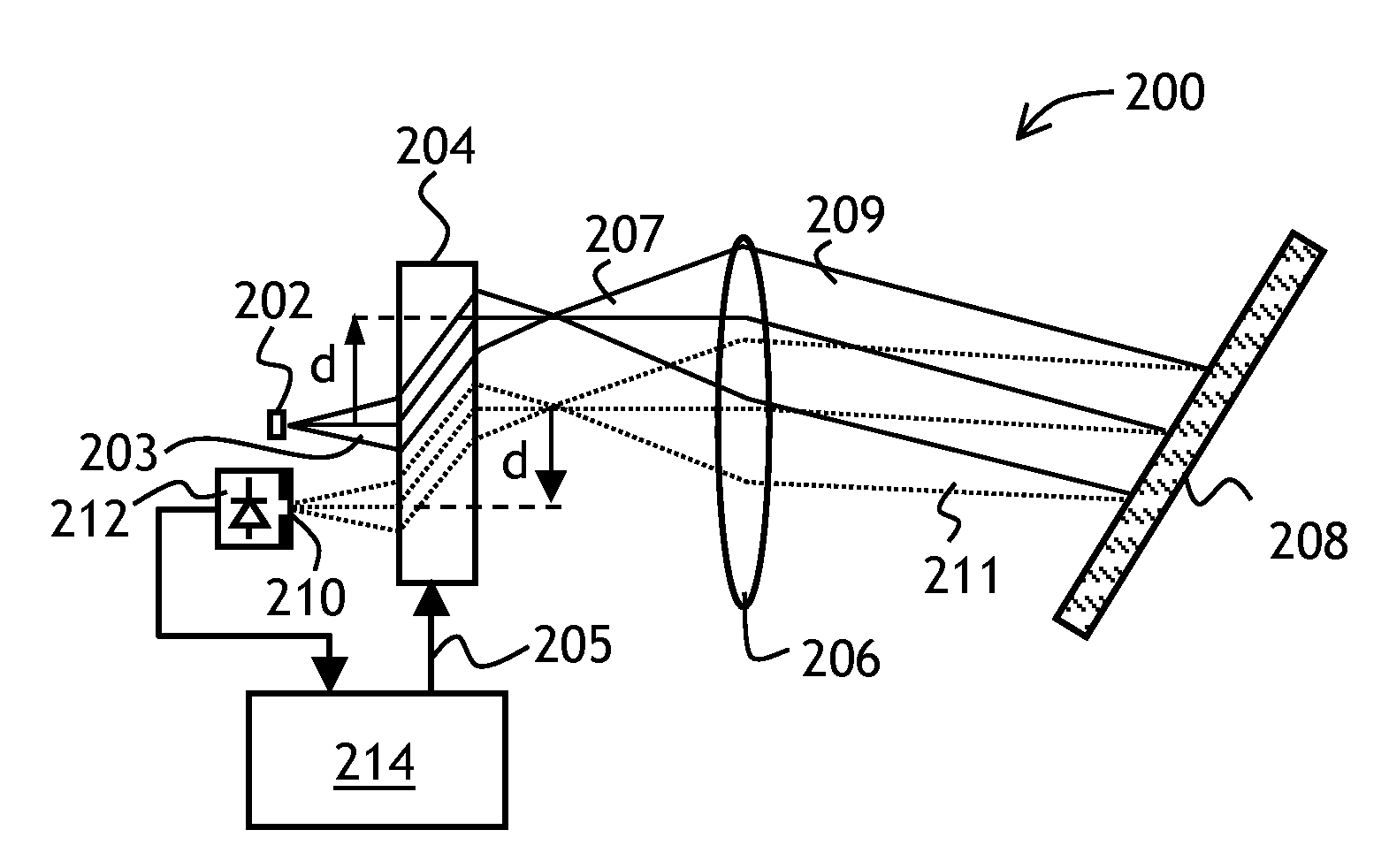
[0042]Referring to FIG. 2A, a spectrometer 200 of the invention includes an input port 202 for providing an input optical beam 203, a beam translator 204 for translating the input optical beam 203 in a plane of FIG. 2A by a controllable distance d, a lens 206 for collimating a translated optical beam 207, a reflective diffraction grating 208 coupled to the lens 206, for angularly dispersing a collimated beam 209 in the plane of FIG. 2A and reflecting a wavelength-dispersed optical beam 211 back towards the lens 206, an output port 210, a photode...


PUM


Abstract

A tunable optical filter is disclosed having an input port, a beam translator for translating input and output optical beams, an element having optical power for collimating the translated beam, a reflective wavelength dispersive element, and an output port. The beam translator can include a tiltable MEMS mirror coupled to an angle-to-offset optical element. An output port can be extended into a plurality of egress ports, each receiving a fraction of the scanned optical spectrum. A multi-path scanning optical spectrometer can be used as an optical channel monitor for monitoring performance of a wavelength selective switch, or for other tasks.

Description

TECHNICAL FIELD[0001]The present invention relates to optical filters, and in particular to tunable optical filters having an optical beam scanning element.BACKGROUND OF THE INVENTION[0002]Tunable optical filters are commonly used in optical devices and systems where an optical spectrum of light needs to be modified, with some wavelengths passing through the filter and some wavelengths blocked by the filter. The wavelengths that are passed by the filter form a band of wavelengths called a transmission band. When the filter is tuned, a central wavelength of the transmission band of the filter is tuned. Tunable optical filters are used in optical communications systems to distinguish between optical signals at different wavelengths carrying different information channels. The optical signals at a single central wavelength are called wavelength channels.[0003]A tunable optical filter is frequently used as a key component of an optical spectrometer. In a scanning optical spectrometer, t...

Claims


Application Information

Patent Timeline
Patent Type & Authority Patents(United States)
IPC IPC(8): G01J3/28
CPCG01J3/18G02B6/29395G02B6/3598G01J3/0294G01J3/021G01J3/027G02B6/2931G02B6/3512G01J2003/062G01J3/32G02B26/0833G02B6/356G02B27/4244G01J3/0218G02B6/3556G01J2003/064G02B26/105G01J3/0291G01J3/0208G01J3/0205
Inventor COLBOURNE, PAULWOODSIDE, SHANE H.BOUEVITCH, OLEG
Owner LUMENTUM OPERATIONS LLC
Learn More