Implementing decoupling devices inside a TSV DRAM stack

a decoupling device and dram stack technology, applied in the field of data processing, can solve problems such as drooping supply voltage and magnified problems

Inactive Publication Date: 2014-04-15
IBM CORP
View PDF11 Cites 17 Cited by
  • Summary
  • Abstract
  • Description
  • Claims
  • Application Information

AI Technical Summary

Benefits of technology

[0005]Principal aspects of the present invention are to provide a method and structures for implementing decoupling capacitors within a DRAM TSV stack. Other important aspects of the present invention are to provide such method and structures substantially without negative effects and that overcome many of the disadvantages of prior art arrangements.
[0007]In accordance with features of the invention, the decoupling capacitors within the TSV DRAM stack minimize the impact of voltage droops when the DRAMs ramp up from a state with low power consumption to a state with high power consumption, such as when the DRAMs ramp up from an idle state to a high utilization state.

Problems solved by technology

If the power supply cannot react in time, this additional current draw will cause a droop in the supply voltage.
When DRAMs are stacked, this issue is magnified due to the additional loading of the master rank any time that a rank is accessed.

Method used


Image

  • Implementing decoupling devices inside a TSV DRAM stack
  • Implementing decoupling devices inside a TSV DRAM stack
  • Implementing decoupling devices inside a TSV DRAM stack

Examples


Embodiment Construction

[0018]In the following detailed description of embodiments of the invention, reference is made to the accompanying drawings, which illustrate example embodiments by which the invention may be practiced. It is to be understood that other embodiments may be utilized and structural changes may be made without departing from the scope of the invention.

[0019]The terminology used herein is for the purpose of describing particular embodiments only and is not intended to be limiting of the invention. As used herein, the singular forms “a”, “an” and “the” are intended to include the plural forms as well, unless the context clearly indicates otherwise. It will be further understood that the terms “comprises” and / or “comprising,” when used in this specification, specify the presence of stated features, integers, steps, operations, elements, and / or components, but do not preclude the presence or addition of one or more other features, integers, steps, operations, elements, components, and / or gr...


PUM


Abstract

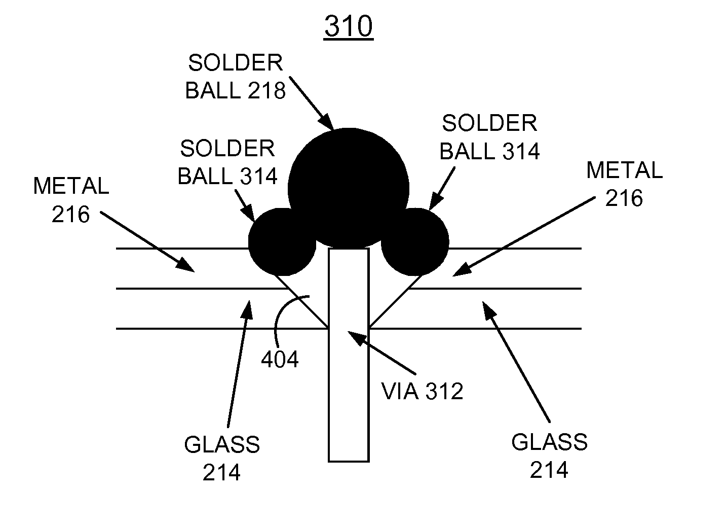
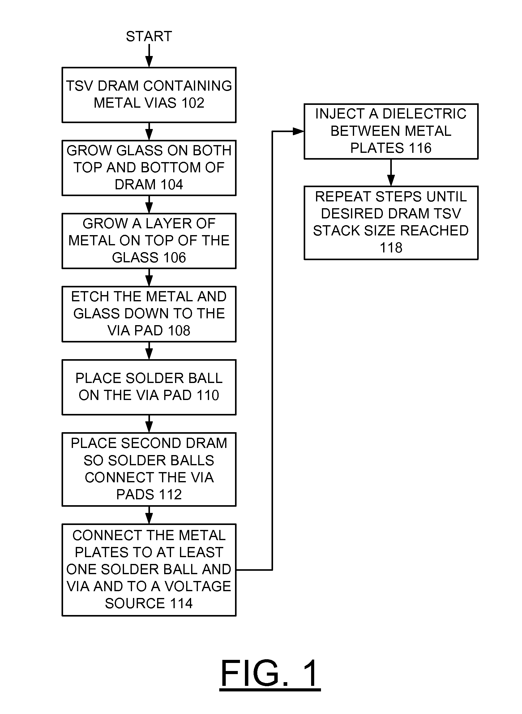
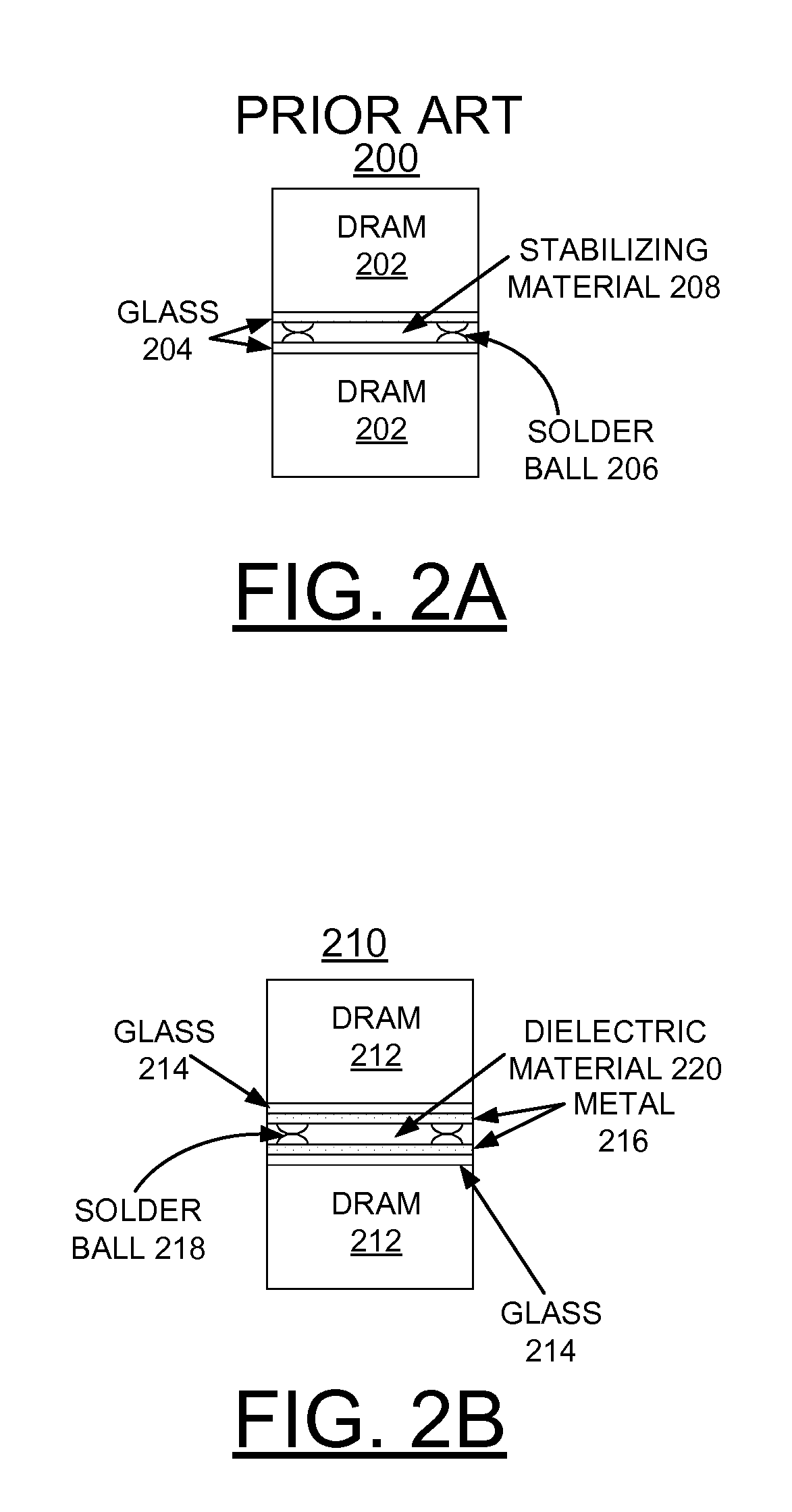
A method and structures are provided for implementing decoupling capacitors within a DRAM TSV stack. A DRAM is formed with a plurality of TSVs extending completely through the substrate and filled with a conducting material. A layer of glass is grown on both the top and bottom of the DRAM providing an insulator. A layer of metal is grown on each glass layer providing a conductor. The metal and glass layers are etched through to TSVs with a gap provided around the perimeter of via pads. A respective solder ball is formed on the TSVs to connect to another DRAM chip in the DRAM TSV stack. The metal layers are connected to at least one TSV by one respective solder ball and are connected to a voltage source and a dielectric is inserted between the metal layers in the DRAM TSV stack to complete the decoupling capacitor.

Description

FIELD OF THE INVENTION[0001]The present invention relates generally to the data processing field, and more particularly, relates to a method and structures for implementing decoupling capacitors within a dynamic random access memory (DRAM) Through-Silicon-Via (TSV) stack.DESCRIPTION OF THE RELATED ART[0002]As circuits become smaller and switching times become faster, the importance of decoupling capacitors increases. For DRAMs it is possible to go from a state with low power consumption to a state with high power consumption very quickly. If the power supply cannot react in time, this additional current draw will cause a droop in the supply voltage. When DRAMs are stacked, this issue is magnified due to the additional loading of the master rank any time that a rank is accessed.[0003]Through-Silicon-Via (TSV) or TSV interconnections are used for various semiconductor chips and semiconductor chip stacking devices. Integrated circuit die stacking with packaging through silicon via (TSV...

Claims


Application Information

Patent Timeline
Patent Type & Authority Patents(United States)
IPC IPC(8): H01L21/768
CPCH01L23/481H01L24/13H01L24/16H01L2224/14051H01L2225/06513H01L2224/05009H01L24/14H01L2225/06541H01L2224/1411H01L23/498H01L2224/13025H01L2224/1613H01L2224/05027H01L21/768H01L2224/131H01L2224/17106H01L2224/13021H01L2224/13014H01L2224/16146H01L2224/73204H01L24/17H01L25/0657H01L2224/0401H01L2924/00012H01L2924/00014H01L2924/014
Inventor HENDERSON, JOAB D.KIM, KYU-HYOUNMAULE, WARREN E.WRIGHT, KENNETH L.
Owner IBM CORP
Why Eureka
Try Eureka