
Heat insulation cell for fuel cell and manufacturing method of the same

a fuel cell and heat insulation technology, applied in the manufacture of final products, cell components, cell component details, etc., can solve the problems of peripheral seal function deterioration, separation deformation, and possible deterioration of seal function

Active Publication Date: 2014-04-15
TOYOTA JIDOSHA KK
View PDF11 Cites 0 Cited by
  • Summary
  • Abstract
  • Description
  • Claims
  • Application Information

AI Technical Summary

Benefits of technology

[0008]To solve this problem, an object of the present invention is to provide a heat insulation cell for a fuel cell which suppresses the deformation of a separator (a plate-like member) or the deterioration of a seal function due to heat generated during power generation, and a manufacturing method of the same.
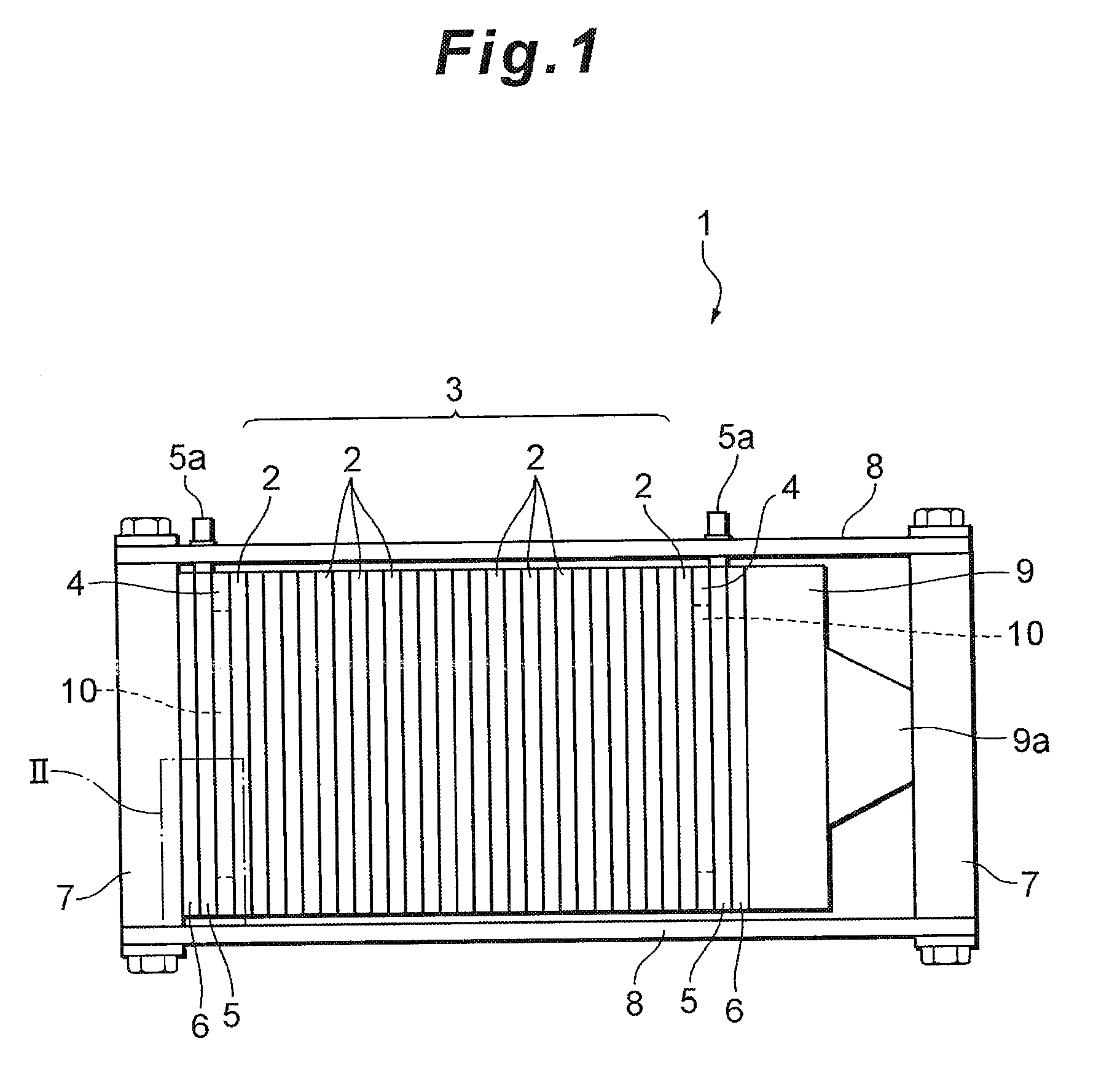
[0009]To achieve such an object, the present inventor has performed various investigations. The above-mentioned heat insulation cell for the fuel cell has a cell structure similar to that of another cell, and is often similar or approximate to the other cell in a portion such as a seal structure using a seal member, except that instead of a membrane-electrode assembly of the other cell, a conductive plate having excellent insulation properties is sandwiched. In this case, a closed air layer formed at the end of a cell stack member (a cell stack) has an advantage that so-called contamination can be suppressed, but has a disadvantage that the seal function might deteriorate as described above. The present inventor has performed further investigations with this point taken into consideration, and has obtained a new finding to achieve such an object.
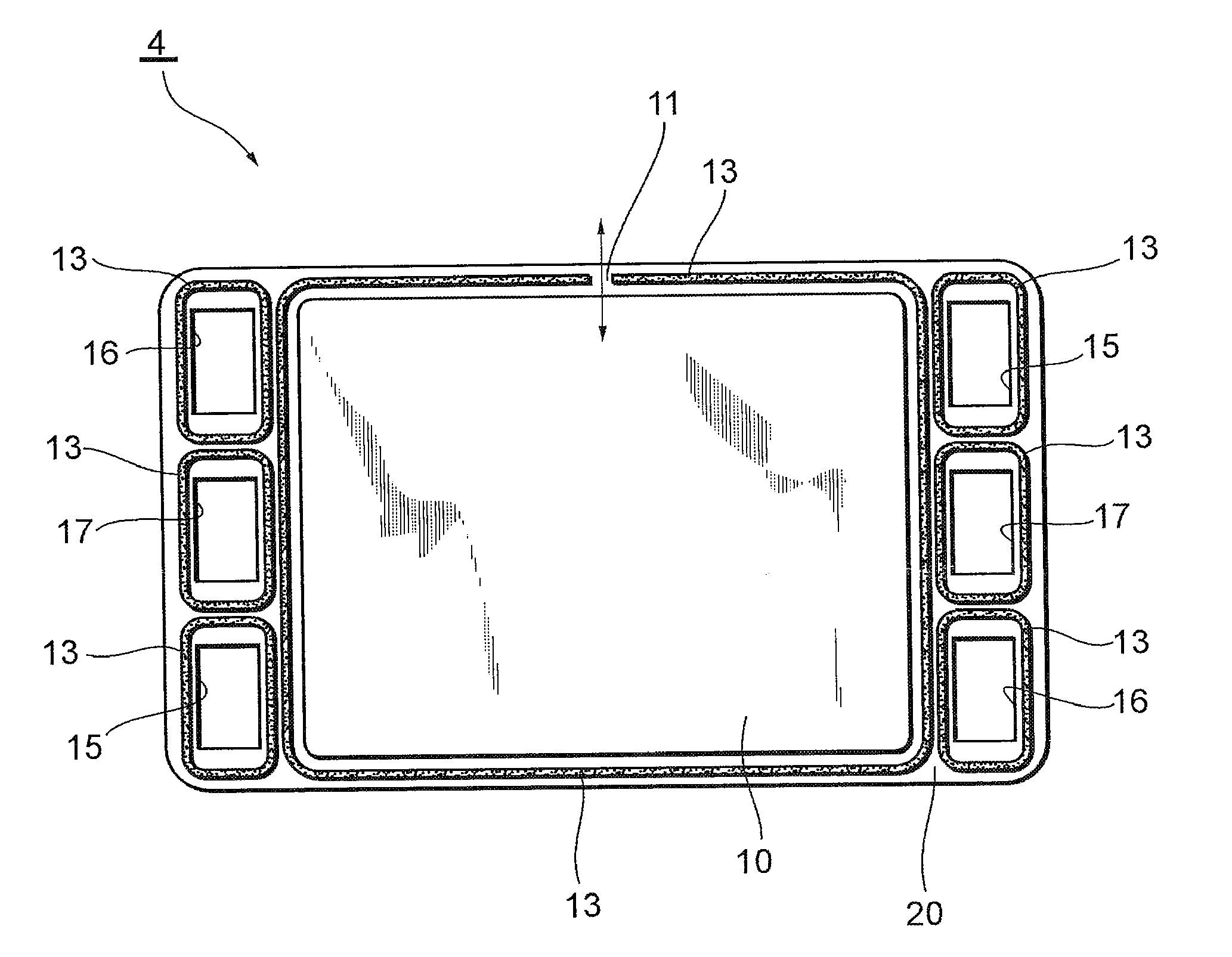
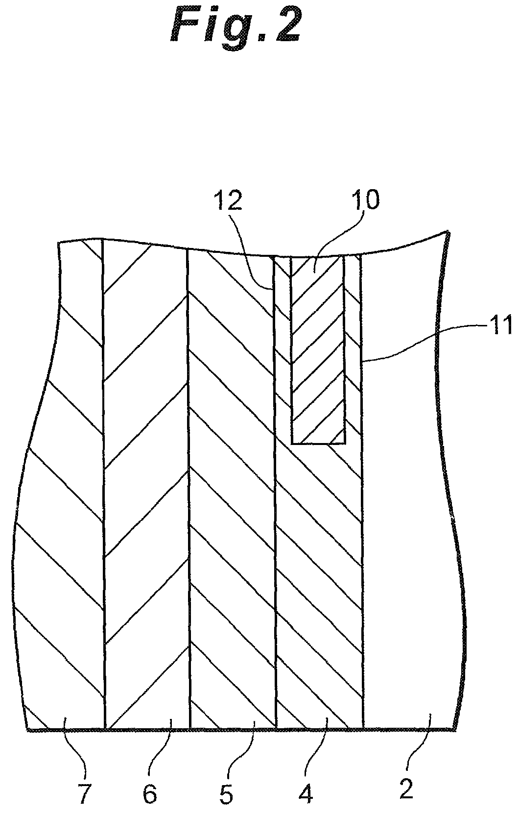
[0012]In the heat insulation cell for the fuel cell according to the present invention, a portion provided with the communication section in at least one of the plate-like members has a projection. The projection disposed on the portion provided with the communication section in this manner can function so that the communication section formed in at least a part of the seal line has a uniform width and so that a region constituting an air hole has a constant size. Moreover, when such a projection is formed so as to abut on, for example, another plate-like member, the projection becomes a stopper for inhibiting the plate-like member from being deformed during the manufacturing of the heat insulation cell. In a case where the seal member is sufficiently pressurized and joined while the seal member does not easily flow, a seal performance can be improved.
[0016]Moreover, according to the present invention, there is provided a manufacturing method of a heat insulation cell for a fuel cell in which an insulation layer is constituted of one or more plate-like members and a seal member, the method comprising the steps of: providing a projection projecting toward another cell on at least one plate-like member, wherein the projection constitutes a discontinued portion in at least a part of the seal member, and the discontinued portion forms a communication section which connects the insulation layer to the outside. In such a case, it is possible to securely form, during the manufacturing, a circulating portion (an air discharge passage) through which a gas (air) in the insulation layer expanded owing to the influence of the heat generated during the power generation can escape to the outside.

Problems solved by technology

However, the influence of heat generated during power generation causes possibilities that a gas in a closed portion of a heat insulation cell for a fuel cell expands and that a separator is deformed or a seal function in a peripheral seal portion deteriorates.
In this case, a closed air layer formed at the end of a cell stack member (a cell stack) has an advantage that so-called contamination can be suppressed, but has a disadvantage that the seal function might deteriorate as described above.

Method used


Image

  • Heat insulation cell for fuel cell and manufacturing method of the same
  • Heat insulation cell for fuel cell and manufacturing method of the same
  • Heat insulation cell for fuel cell and manufacturing method of the same

Examples


fourth embodiment

[0057]It is to be noted that in the above fourth embodiment, the heat insulation cell 4 having the structure including the projecting portions 21 formed on one surface or both surfaces of the communication section constituting member 22 has been illustrated (see FIGS. 7 to 10), but a similar function can be realized by a structure different from this structure. That is, although not especially shown, for example, similar projecting portions 21 may be formed on one or both of the separators 20 instead of forming the projecting portions 21 on the communication section constituting member 22. Alternatively, the projecting portions 21 may be formed on both of the communication section constituting member 22 and the separator 20.

[0058]

[0059]In the above-mentioned embodiments, a structure has been illustrated in which at least a part of a seal member (a seal line) 13 is partially disconnected (discontinued) to form a communication section 11, but a structure can be realized in which the c...

first embodiment

[0064]Moreover, for example, in the first embodiment, the insulation member 10 smaller than the seal member (the seal line) 13 has been illustrated (see FIG. 3), but as another example, the insulation member 10 having a size approximately equal to that of the seal member (the seal line) 13 or the like may be used and superimposed on the communication section 11. For example, in a structure in which a part of an insulation member is sandwiched between two plate-like members (separators), the sandwiched part of the insulation member can function so as to suppress the deformation of the separators due to the influence of an external force.

Industrial Applicability

[0065]According to the present invention, it is possible to suppress the deformation of a separator (a plate-like member) in a heat insulation cell due to heat generated during power generation and the deterioration of a seal function.

[0066]Therefore, the present invention can broadly be utilized in a heat insulation cell for a...


PUM

PropertyMeasurementUnit
structureaaaaaaaaaa
temperatureaaaaaaaaaa
internal pressureaaaaaaaaaa

Abstract

The deformation of a plate-like member (a separator) or the degradation of a seal function due to heat generated during power generation is suppressed. To realize this, disclosed is a heat insulation cell for a fuel cell in which an insulation layer is constituted of one or more plate-like members and a seal member, the heat insulation cell being provided with a communication section which is disposed in at least a part of a seal line formed by the seal member to seal the insulation layer and the outside of the cell and which connects the insulation layer to the outside. A portion provided with the communication section in at least one of the plate-like members preferably has a projection. It is also preferable that the insulation layer is formed by an insulation member and that the insulation member is disposed in the communication section.

Description

[0001]This is a 317 national phase application of PCT / JP2007 / 075225 filed 20 Dec. 2007, which claims priority to Japanese Patent Application No. 2007-000497 filed 5 Jan. 2007, the contents of which are incorporated herein by reference.BACKGROUND OF THE INVENTION[0002]1. Field of the Invention[0003]The present invention relates to a heat insulation cell for a fuel cell and a manufacturing method of the same. More particularly, the present invention relates to the improvement of a structure of a heat insulation cell for a fuel cell.[0004]2. Description of Related Art[0005]In general, a fuel cell (e.g., a polymer electrolyte fuel cell) has a constitution in which a plurality of cells each including an electrolyte sandwiched between separators are stacked, but at the end of a stack member (a cell stack) including the stacked cells in a stack direction, a temperature easily lowers owing to heat exchange between the end and the atmosphere. Meanwhile, a constitution is known in which, for ...

Claims


Application Information

Patent Timeline
Patent Type & Authority Patents(United States)
IPC IPC(8): H01M8/04H01M2/08
CPCH01M8/0267Y02E60/50H01M8/0273H01M8/242H01M2008/1095H01M8/0297Y10T29/49108Y02P70/50H01M8/2483
Inventor KATO, CHISATO
Owner TOYOTA JIDOSHA KK
Learn More