
System for controlled on demand in situ hydrogen generation using a recyclable liquid metal reagent, and method used in the system

a technology of metal reagent and recycling liquid, which is applied in the field of chemical generation of hydrogen, can solve the problems of difficult control, high cost, and high volume of hydrogen gas, and achieve the effect of improving the level of control over the reaction and the safety and performance of the hydrogen generation process, and being easy to control

Active Publication Date: 2014-04-15
GARRIDO ESCUDERO AMALIO
View PDF16 Cites 2 Cited by
  • Summary
  • Abstract
  • Description
  • Claims
  • Application Information

AI Technical Summary

Benefits of technology

[0023]The ratio “interface surface within both reagents (demineralized water and liquid metal / metal alloy / liquid metal) / mass per volume unit” enhances the level of control over the reaction and the safety and performance of the hydrogen generation process. This ratio can be set up by optimizing, among other parameters, the diameters of the injection pipes, reactor length, flow velocity, flow stream pressures and temperatures. Laminar flow conditions have the advantage that hydrogen generation is normally easier to control than under turbulent flow conditions.
[0058]As apparent, according to the present invention, the recovery of metal reagent from the residual reaction product allows efficient recycling of the metal reagent from the metal hydroxide as present in the residual reaction product produced when hydrogen is generated. The recovery is based on the following reaction scheme that, although specifically referring to alkali metals, is also applicable to Mg by analogy:
[0068]Further, by adequately selecting the metal reagent or alloys thereof, the invention allows operating at low pressures including pressures below 2 bar, and within substantially lower temperature ranges, e.g. between −14° C. and 180° C. than known prior art systems. These conditions are advantageous inasmuch the system of the invention is to be designed to stand only relatively low temperatures and pressures and, moreover, it is a technical solution that allows controlling the per se violent reaction and thereby controllably producing hydrogen on demand without deflagrations. Furthermore, the invention needs only a small input of energy to start the reaction and leads to easily separable hydrogen, as hydrogen is the only gas produced in the reaction at ambient temperature. The system of the invention may be designed for hydrogen generation to fit in vehicles, apparatus requiring energy input, or in off-line stationary plants such as power plants.
[0072]One advantage of the system of the present invention when implemented in a vehicle is that the weight of the system is rather constant inasmuch the metal hydroxide as produced has a very similar weight to that of the metal reagent. Thus, when the recovery system is not implemented in the vehicle, the weight of fresh metal reagent fed into the first storage means is practically equivalent to that of the metal hydroxide that is removed, whilst when the recovery system is also implemented in the vehicle, the weight of the recovered metal reactant is practically equivalent to the weight of the metal hydroxide produced.

Problems solved by technology

As apparent, the density by volume of hydrogen gas is extremely low so that storage thereof in vehicle tanks or stationary tanks raises efficiency problems.
The reactions underlying this method are violent, take place at very high temperatures and pressures, and are thus difficult to control.
This renders the method disclosed in US-3985866 rather unfeasible in industrial practice.
The majority of conventional hydrogen generating systems requires catalysts and / or ignition systems are expensive with regard to recycling the fuel or use highly toxic substances.
Whilst a major proportion of these systems is susceptible of being installed in motor vehicles, they still are technically complex or involve technical, economical or environmental drawbacks, especially in respect of providing sufficient precision and sensitivity of generating a stream of hydrogen that may allow an immediate response to power demands as, for example, by direct injection thereof into an internal combustion motor or a turbine, and in respect of recycling fuel used.

Method used


Image

  • System for controlled on demand in situ hydrogen generation using a recyclable liquid metal reagent, and method used in the system
  • System for controlled on demand in situ hydrogen generation using a recyclable liquid metal reagent, and method used in the system
  • System for controlled on demand in situ hydrogen generation using a recyclable liquid metal reagent, and method used in the system

Examples


Embodiment Construction

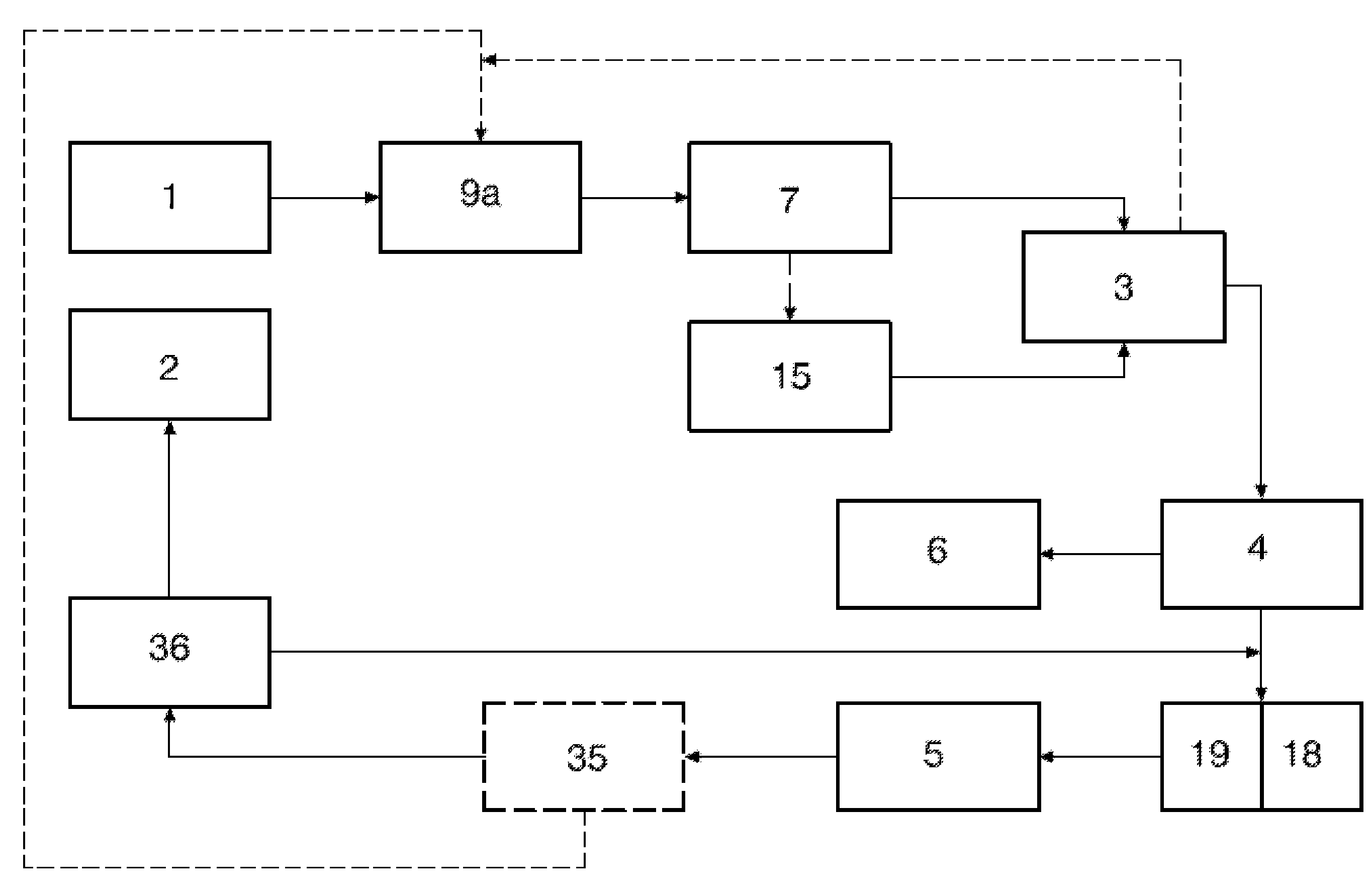
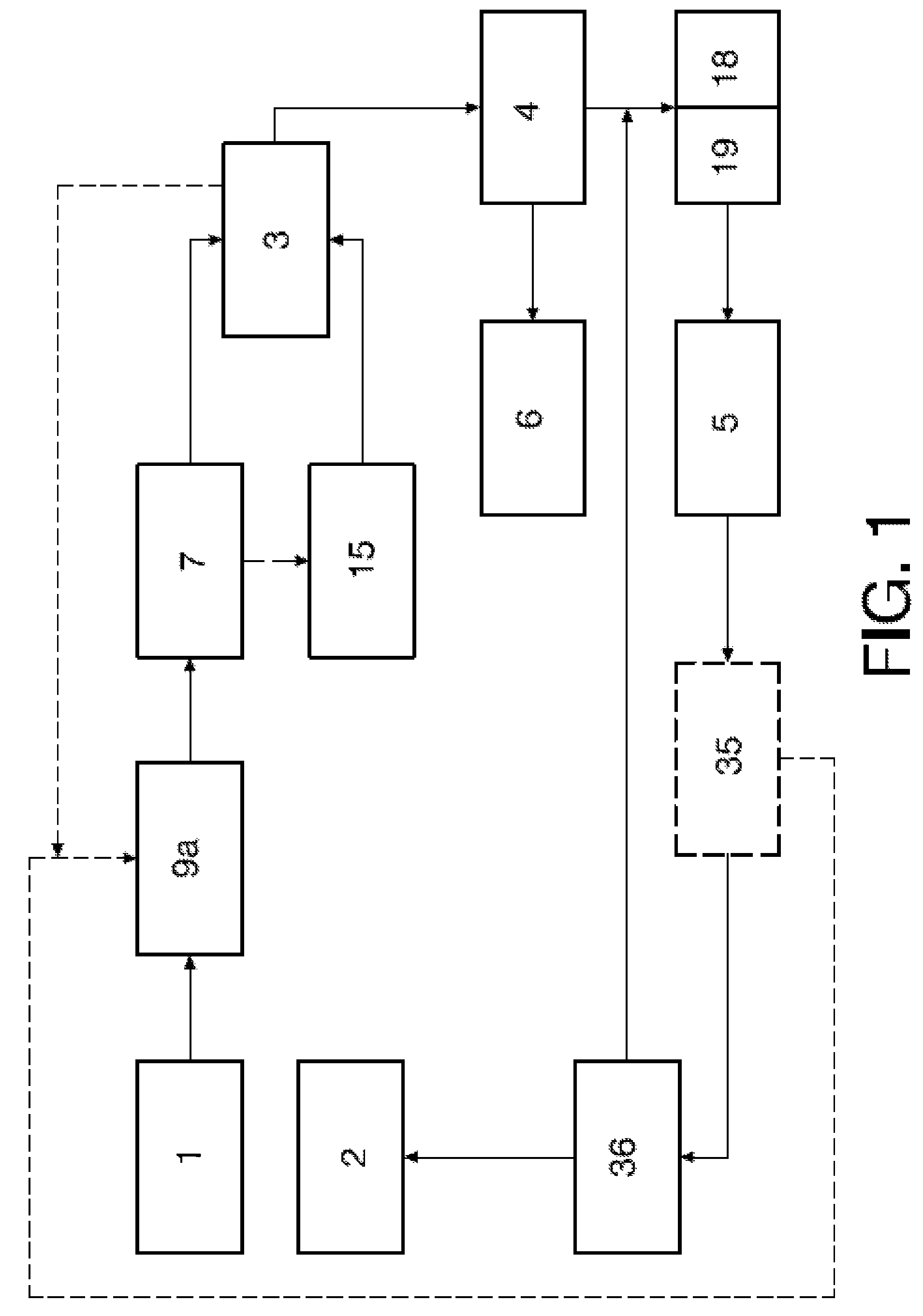
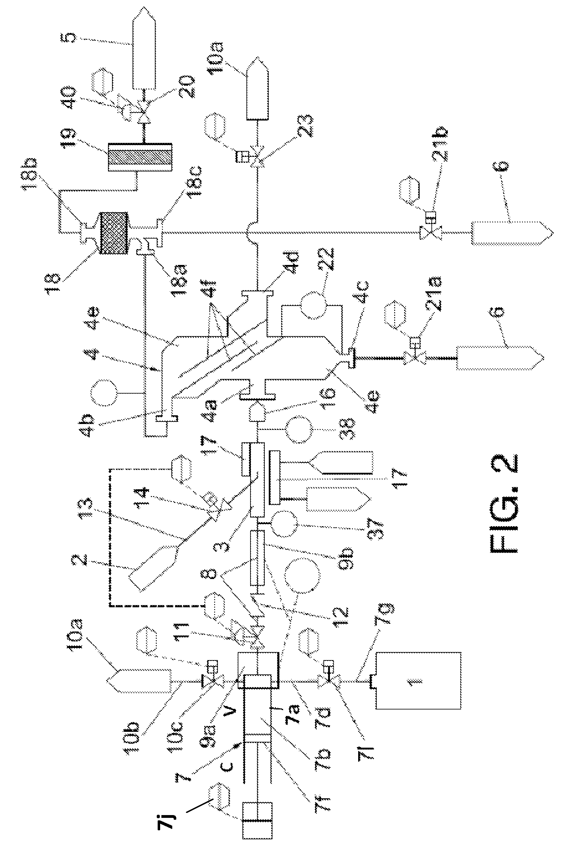
[0082]FIGS. 1 to 3 show the basic steps and elements of hydrogen generation in accordance with an embodiment of the invention.

[0083]The basic steps of this embodiment are shown in FIG. 1 and will be explained on the basis of an alkali metal such as lithium or sodium being used as the first reagent although these steps can also be followed analogously using alkaline earth metal, or alloys of these metals.

[0084]Alkali metal contained in the first storage means -1- is heated by first reagent heating means -9a- to a temperature above its melting point, and the so liquefied alkali metal is injected by extrusion, preferably using a controlled dimension extruder die head, into the reactor -3- by means of the metal reagent injecting device -7-. Simultaneously, demineralized cool liquid water coming from the second storage means -2- is also injected into the reactor -3- by water-injection means -15-. The water-injecting means -15- is controlled such that it provides a water flow that is at a...


PUM

PropertyMeasurementUnit
melting pointaaaaaaaaaa
temperatureaaaaaaaaaa

Abstract

A hydrogen generating system and a method of in situ hydrogen generation controlled on demand capable of reacting an aluminum-free metal reagent composed of at least one of alkali metals, alkaline earth metals, alkali metal alloys and blends including alkali metals, alkaline earth metal alloys and blends including alkaline earth metals and metal alloys including at least one alkali metal and at least one alkaline earth metal, with water to obtain hydrogen and a residual reaction product including metal hydroxide composed of at least one of alkali hydroxides and alkaline earth hydroxide; and separating hydrogen from the residual reaction product; liquefying the metal reagent by heating to obtain liquid metal reagent under vacuum conditions; injecting the liquid metal reagent into a reactor by metal reagent injecting means and simultaneously injecting, by water injection system, a stoichiometric amount of water with respect to the amount of the liquid metal reagent being injected into the reactor such that a controlled metal reagent / water ratio is maintained in the reactor; transferring hydrogen and the residual reaction product from the reactor to separation means; separating hydrogen from the residual reaction product; transferring separated hydrogen to hydrogen receiving means and transferring the residual reaction product to metal hydroxide receiving means, keeping the metal reagent injecting means water injection system, the reactor, the separating means and the hydrogen receiving means free of oxygen by selectively providing a vacuum in the system.

Description

TECHNICAL FIELD OF THE INVENTION[0001]The present invention lies within the technical field of chemical generation of hydrogen using alkali metals and alkaline earth metals, and recovery of alkali metals and alkaline earth metals from the corresponding hydroxides.[0002]The invention is particularly useful in the generation of hydrogen in amounts that are controllably produced in response to varying demands thereof as, for example in vehicles with internal combustion engines, turbines or hydrogen cells such as vehicles for locomotion by land, air or water etc., and any other apparatus requiring on demand hydrogen generation for any purpose.BACKGROUND OF THE INVENTION[0003]Hydrogen can be used as non-polluting fuel in fuel cells, internal combustion engines or turbines, as well as in any other system where gaseous hydrogen is used as a fuel. Obviously, power generating systems using hydrogen as a fuel need the hydrogen to be produced by a generating process. Generally, hydrogen produc...

Claims


Application Information

Patent Timeline
Patent Type & Authority Patents(United States)
IPC IPC(8): C01B3/38C01B3/24B01J7/00
CPCY02E60/50C01B2203/0465B01J10/005Y02T90/32H01M2250/20C01B2203/169C01B3/50H01M8/04208B01J4/008Y02E60/36C01B3/08C01B3/10Y02T90/40B01J4/02
Inventor GARRIDO, ESCUDERO, AMALIO
Owner GARRIDO ESCUDERO AMALIO
Learn More