
Composite washing system

a washing system and composite technology, applied in the field of drying equipment, can solve the problems of inability to maintain laundry in the dryer, inability to be built-in type, inefficient drying of laundry,

Inactive Publication Date: 2014-04-15
LG ELECTRONICS INC
View PDF312 Cites 25 Cited by
  • Summary
  • Abstract
  • Description
  • Claims
  • Application Information

AI Technical Summary

Benefits of technology

The invention is a washing system that can dry clothes in a drying machine and a drying cabinet at the same time. It uses continuously circulating air to ensure even drying of the clothes in the drying cabinet. This leads to better and more complete drying results.

Problems solved by technology

In the conventional drum dryer, however, there is a problem in that laundry is inefficiently dried because the drying cycle is carried out while the laundry is in an entangled state.
Furthermore, there is a problem in that the laundry cannot be maintained in the dryer.
However, the above-mentioned combination type dryer has a problem in that it cannot be of a built-in type because it has an air discharge type structure in which the air used to dry laundry is outwardly discharged from the dryer.
For this reason, the appearance of the dryer is unattractive.
Furthermore, the air discharged from the combination type dryer is hot and humid, thereby causing the indoor environment to be an environment undesirable for the user, namely, a high-temperature and humid environment.
In addition, hot air is supplied to the laundry laid on shelves or hung on hangers in the drying cabinet at limited positions, so that a part of the laundry may be excessively dried, and another part of the laundry may be incompletely dried.
For this reason, there are problems of a reduced drying performance of the laundry dryer, and damage to the laundry caused by excessive drying.

Method used


Image

  • Composite washing system
  • Composite washing system
  • Composite washing system

Examples


Embodiment Construction

[0055]Reference will now be made in detail to the preferred embodiments of the present invention, examples of which are illustrated in the accompanying drawings. Wherever possible, the same reference numbers will be used throughout the drawings to refer to the same or like parts.

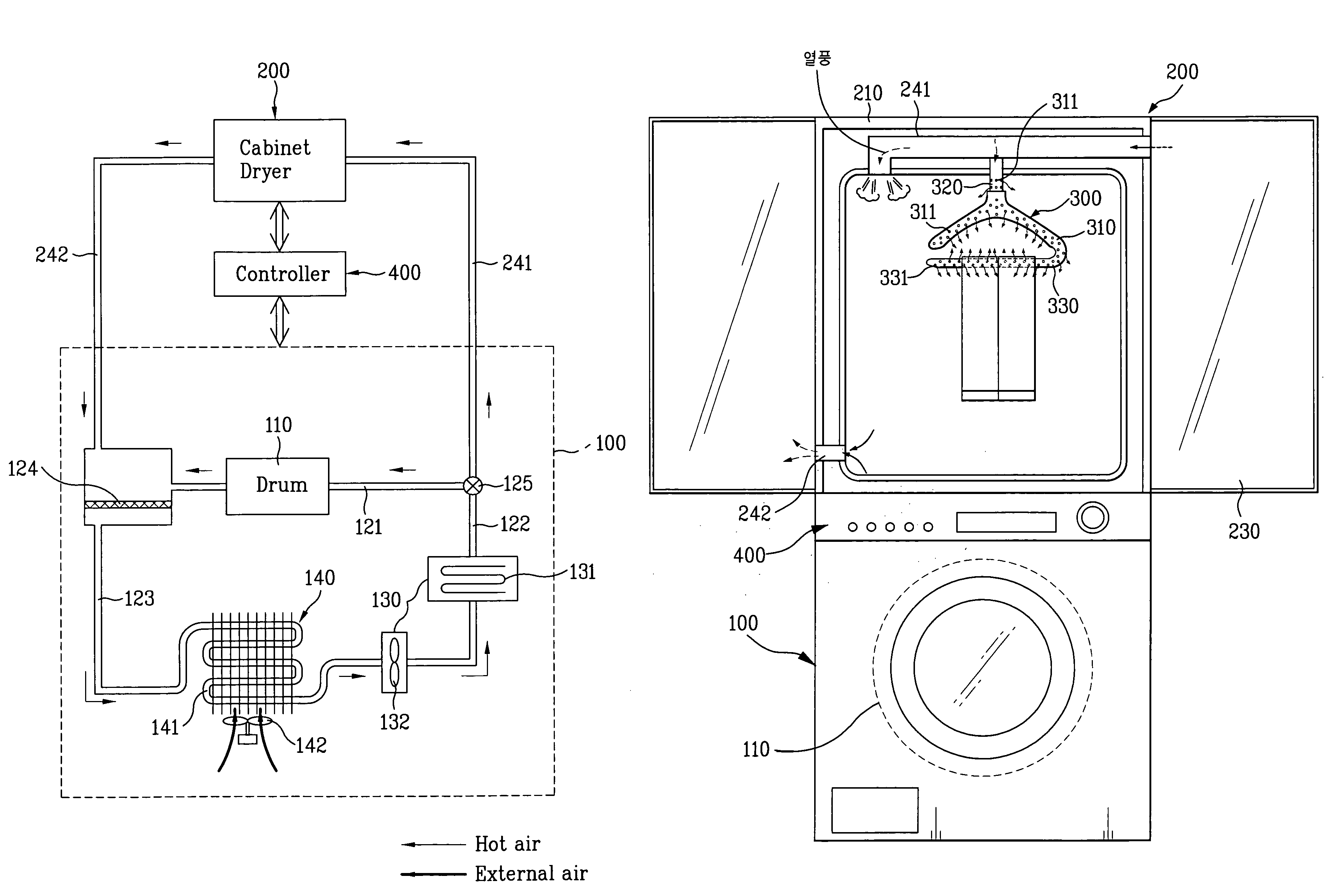
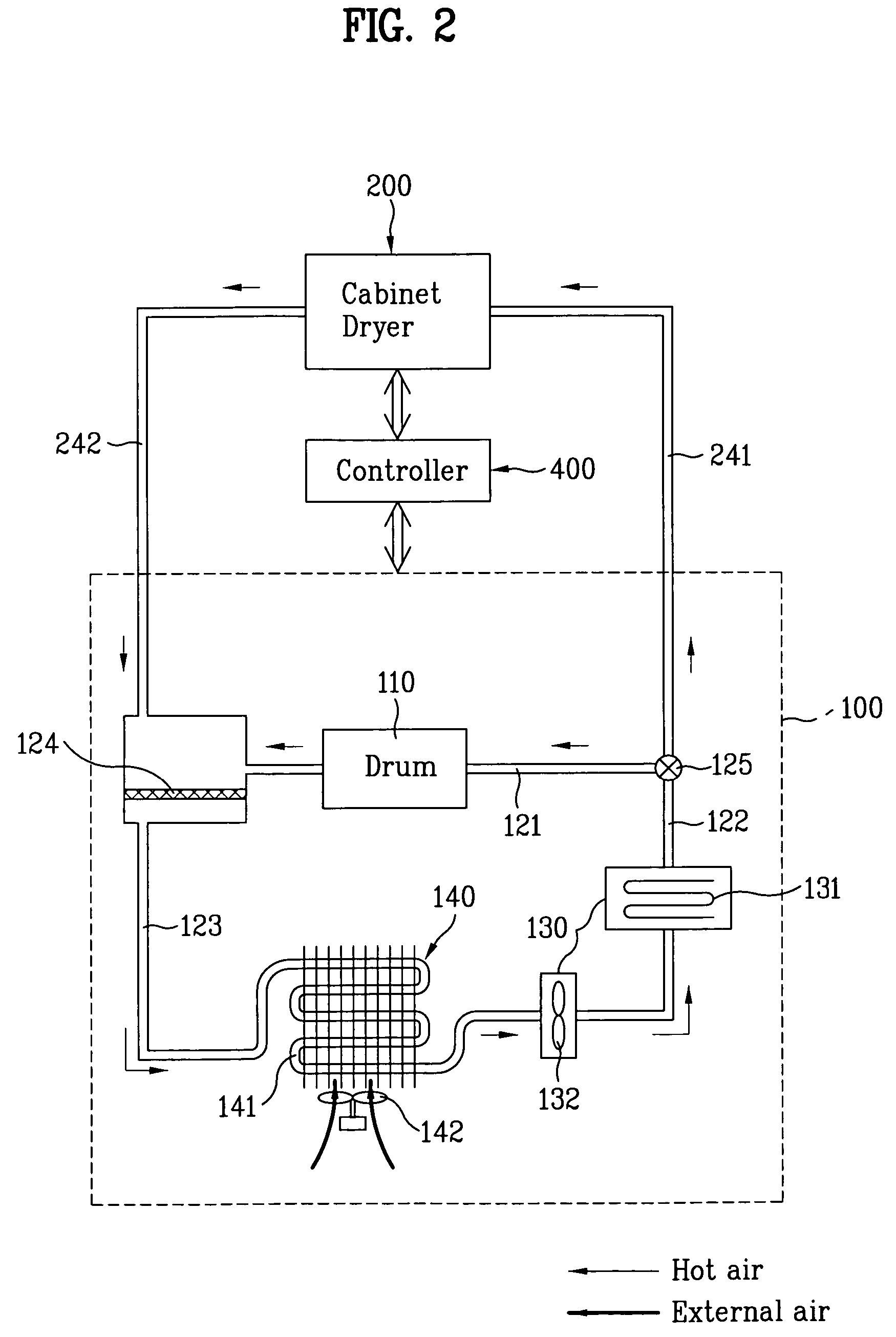
[0056]FIG. 2 is a block diagram schematically illustrating a configuration of a composite washing system according to an exemplary embodiment of the present invention. FIG. 3 is a front view schematically illustrating the configuration of the composite washing system according to the exemplary embodiment of the present invention.

[0057]FIG. 4 is a perspective view illustrating a hot air supplying device according to an exemplary embodiment of the present invention. FIG. 5 is a front view schematically illustrating use of the hot air supplying device according to the exemplary embodiment of the present invention.

[0058]As shown in FIGS. 2 and 3, the composite washing system according to the exemplary embodiment...


PUM


Abstract

A composite washing system is disclosed which is capable of continuously circulating laundry-drying air through dryers while obtaining a more efficient drying effect, so that the composite washing system has a suitable built-in structure having minimal influence on the indoor environment. The composite washing system includes a drum dryer which dries laundry to be dried, and includes a drying drum adapted to receive the laundry, a hot air supply path adapted to guide a flow of hot air, a hot air supplier arranged in the hot air supply path to generate the hot air, and an air condenser adapted to condense the hot air, a cabinet dryer which is coupled to one side of the drum dryer, and is defined with a laundry receiving compartment, the cabinet dryer including a hot air inlet duct adapted to receive the hot air flowing through the hot air supply path, and a hot air supplying device which is arranged in the cabinet dryer to receive the hot air from the hot air inlet duct and to supply the received hot air to an inside of the laundry.

Description

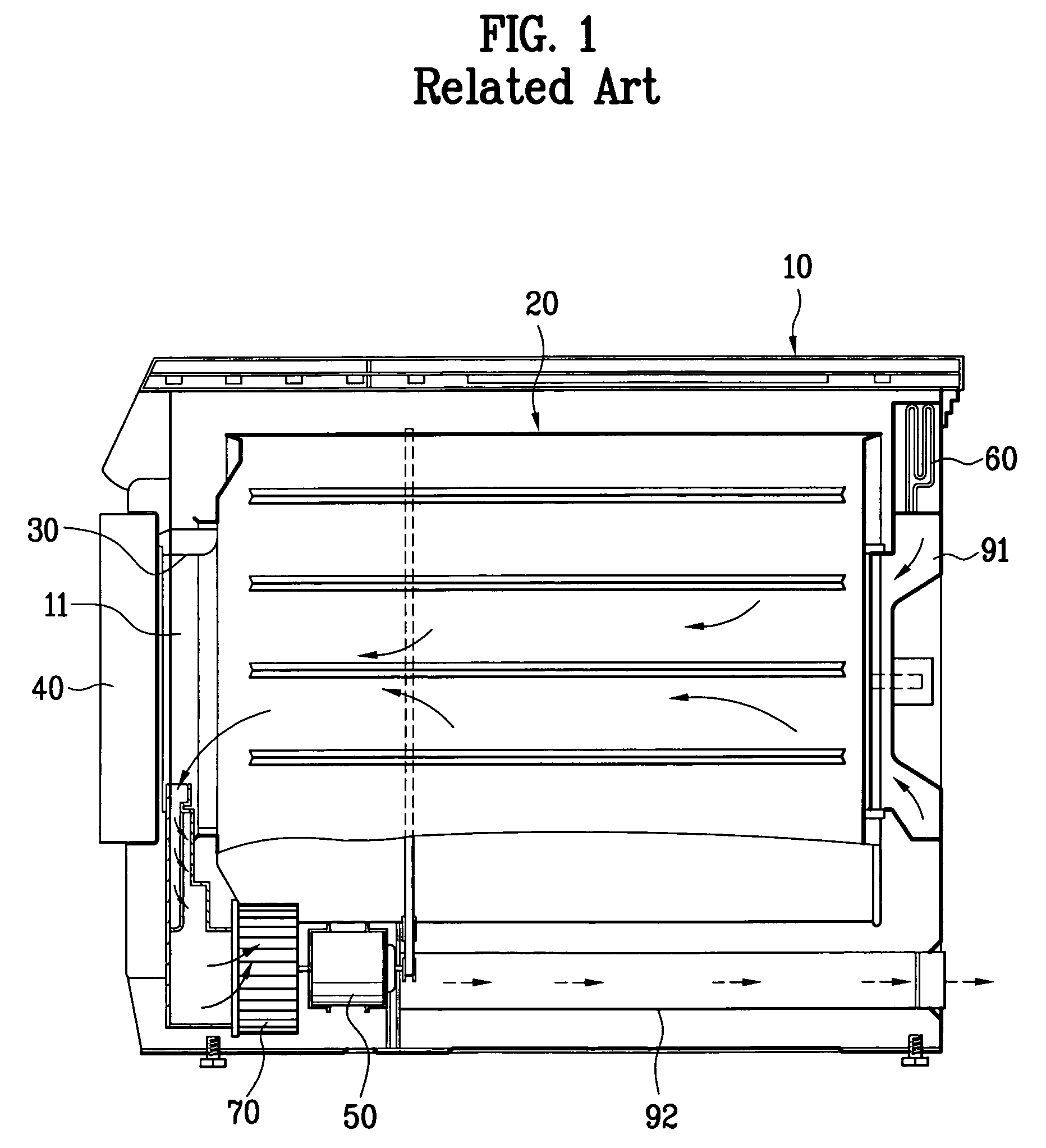
[0001]This application claims the benefit of Korean Patent Application No. P2004-99134 filed on Nov. 30, 2004 which is hereby incorporated by reference as if fully set forth herein.BACKGROUND OF THE INVENTION[0002]1. Field of the Invention[0003]The present invention relates to a drying apparatus, and more particularly, to a composite washing system which is capable of continuously circulating laundry-drying air through dryers while obtaining a more efficient drying effect, so that the composite washing system has a suitable built-in structure.[0004]2. Discussion of the Related Art[0005]Generally, laundry dryers are adapted to dry laundry such as clothes. Such a laundry dryer receives completely-washed laundry, and then performs an operation to dry the laundry while continuously supplying hot air.[0006]FIG. 1 illustrates a general drum dryer as an example of a conventional laundry dryer.[0007]As shown in FIG. 1, the conventional drum dryer mainly includes a body 10, a drying drum 20,...

Claims


Application Information

Patent Timeline
Patent Type & Authority Patents(United States)
IPC IPC(8): F26B19/00
CPCD06F73/02D06F58/20D06F58/10D06F34/26D06F58/38D06F2103/08D06F2103/32D06F2103/36D06F2105/20D06F2105/30
Inventor LEE, DEUG HEECHO, HUNG MYONGAHN, BYUNG HWANCHOI, SOUNG BONGKIM, YOUNG SOO
Owner LG ELECTRONICS INC
Learn More