
Neural network system

a neural network and reconfigurable technology, applied in the field of reconfigurable neural network systems, can solve the problems of affecting the implementation efficiency of neural networks, affecting the application range, and affecting the effect of circuit resources,

Active Publication Date: 2014-04-08
PIECE FUTURE PTE LTD
View PDF20 Cites 5 Cited by
  • Summary
  • Abstract
  • Description
  • Claims
  • Application Information

AI Technical Summary

Benefits of technology

The present invention is a neural network system that can minimize circuit resources and be reconfigured for different purposes. It includes a von Neumann-type microprocessor and a reconfigurable neural network engine that works together to perform backward propagation and sequential program processing. By doing so, the system can minimize the circuit resources required for self-learning and be reconfigured for various purposes. The reconfigurable engine can complement the processes that may not be suitable for the microprocessor, and the microprocessor can change the network configuration in various ways. Therefore, the present invention allows for efficient and flexible training of neural networks.

Problems solved by technology

However, the foregoing implementation methods have the following drawbacks.
Further, since the network configuration is fixed the applicable range is limited.
To give a higher degree of freedom to the network configuration, circuit resources for the self-learning mechanism that satisfy the desired degree of freedom are required, which makes the implementation more difficult.
In the case of the implementation by software, utilizing the software for emulating the neural network model is time-consuming in terms of the reaction of the neuron cells and hence unsuitable for real-time processing, which leads to limited applications.
Further, the neural network is, intrinsically, excellent in cognitive processes but not suitable for sequential program processing, which also leads to limited applications.

Method used


Image

  • Neural network system
  • Neural network system
  • Neural network system

Examples


embodiment 1

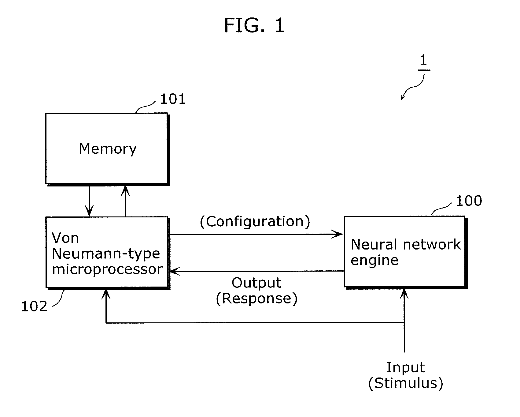
[0067]FIG. 1 is a block diagram of a neural network system according to an embodiment 1.

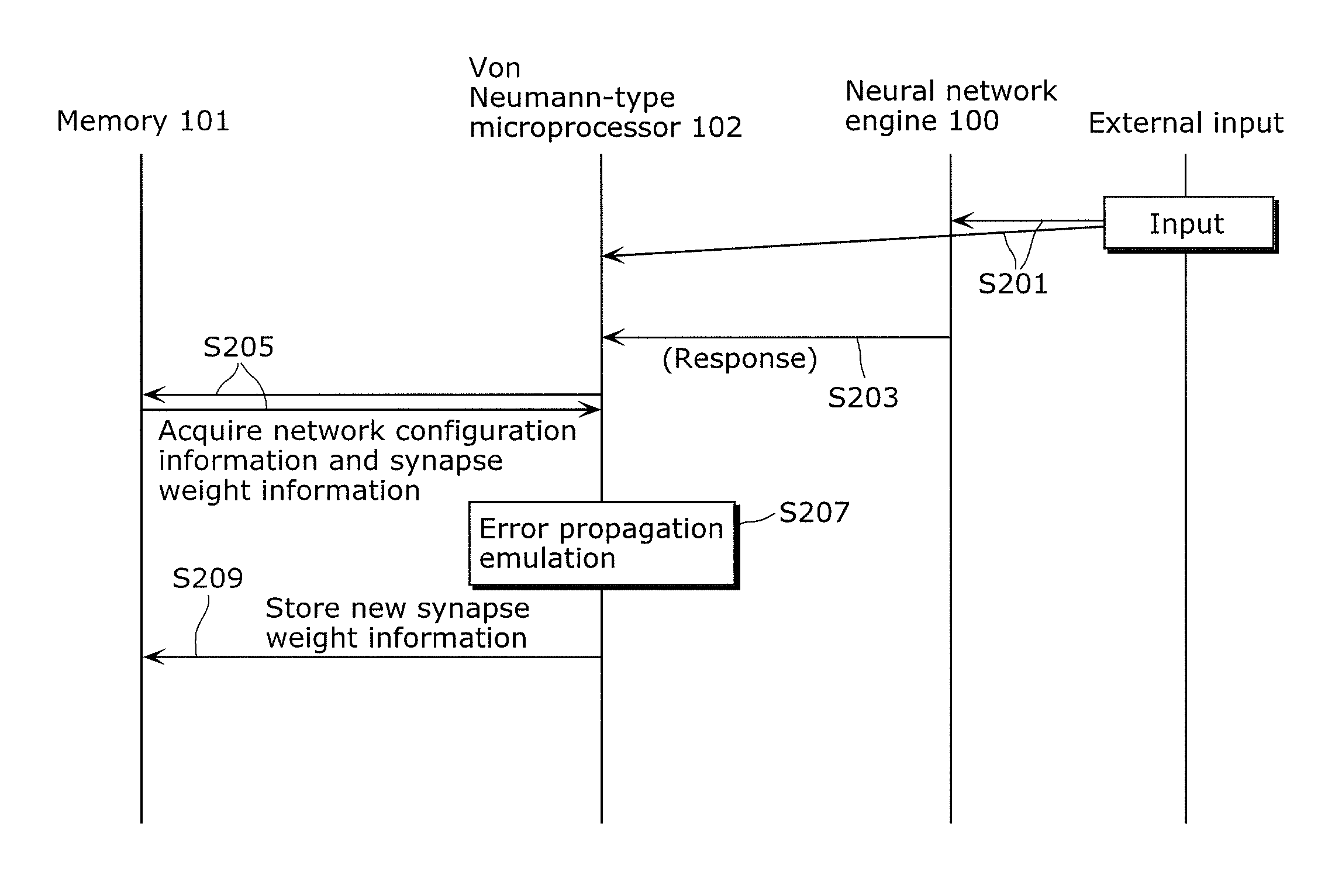
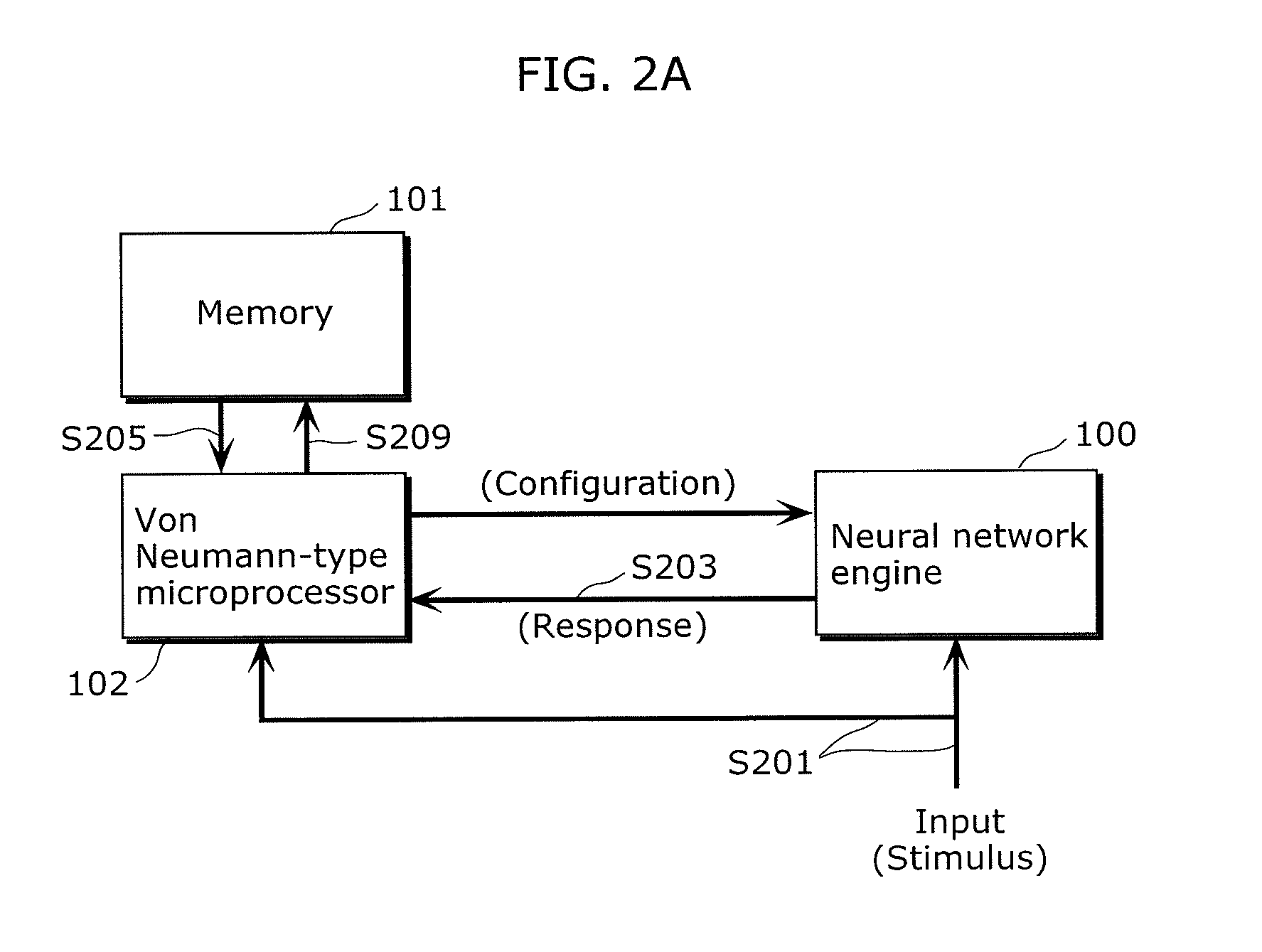
[0068]The neural network system 1 shown in FIG. 1 includes a neural network engine 100 that can operate in a plurality of operation modes, a memory 101, and a von Neumann-type microprocessor 102.

[0069]In the neural network system 1, the neural network engine 100 and the von Neumann-type microprocessor 102 perform a cooperative operation in accordance with the operation modes, to thereby obtain a desired operation result.

[0070]The neural network engine 100 is connected to the von Neumann-type microprocessor 102. The neural network engine 100 performs an operation (reaction) representing a characteristic determined by setting network configuration information indicating a network configuration to be formed and synapse weight information indicating a weight with respect to the network configuration. The neural network engine 100 also performs a reaction (operation) to an input (stimulus) from outsid...

embodiment 2

[0113]An embodiment 2 represents a specific example of the configuration of the neural network engine 100.

[0114]FIGS. 6A and 6B are schematic plan views of the neural network engine according to the embodiment 2.

[0115]The neural network engine 100 according to the embodiment 2 includes, as shown in FIGS. 6A and 6B, neural processing elements (NuPE) 400 that each perform neural signal processing, routing switches 401, memories 402 containing control information of the neural processing element 400, memories 403 containing control information of the routing switch 401, and interconnects 404.

[0116]As shown in FIG. 6B, the neural processing elements 400 and the routing switches 401 are alternately (in a checkerboard pattern) arranged and connected through the interconnects 404. Accordingly, any given neural processing elements 400 can communicate with each other through the routing switches 401.

[0117]FIGS. 7, 8, and 9 illustrate a configuration of the neural processing element. FIG. 7 i...

embodiment 3

[0135]An embodiment 3 represents an application example of the neural network system 1.

[0136]FIGS. 10A and 10B are diagrams for explaining an application example of a neural network system according to the embodiment 3. Referring to these drawings, a process performed by the neural network engine 100 and the von Neumann-type microprocessor 102 for deciding a feature will be described.

[0137]The neural network engine 100 shown in FIG. 10A constitutes a Gabor filter. The Gabor filter, which is known as a model of the initial visual field (V1) of a brain, is also known to be useful as a feature extraction model.

[0138]For the neural network engine 100, the network configuration information indicating the network configuration that constitutes the Gabor filter, and the synapse weight information indicating the characteristic of the Gabor filter in that network configuration are set by the von Neumann-type microprocessor 102.

[0139]An operation of the neural network engine 100 will be descr...


PUM


Abstract

A neural network system that can minimize circuit resources for constituting a self-learning mechanism and be reconfigured into network configurations suitable for various purposes includes a neural network engine that operates in a first and a second operation mode and performs an operation representing a characteristic determined by setting network configuration information and weight information with respect to the network configuration, and a von Neumann-type microprocessor that is connected to the neural network engine and performs a cooperative operation in accordance with the first or the second operation mode together with the neural network engine. The von Neumann-type microprocessor recalculates the weight information or remakes the configuration information as a cooperative operation according to the first operation mode, and sets or updates the configuration information or the weight information set in the neural network engine, as a cooperative operation according to the second operation mode.

Description

CROSS REFERENCE TO RELATED APPLICATION[0001]This is a continuation application of PCT application No. PCT / JP2009 / 004483 filed on Sep. 10, 2009, designating the United States of America.BACKGROUND OF THE INVENTION[0002](1) Field of the Invention[0003]The present invention relates to a reconfigurable neural network system.[0004](2) Description of the Related Art[0005]Methods of performing cognitive signal processing such as face recognition and sound recognition utilizing a neural network are widely known.[0006]The neural network simulates a signal processing system constituted of a neuron network in a human's brain, to perform neural signal processing in which mutually connected neuron cells operate in parallel. Such a process allows objects that are difficult to formularize, such as data containing a noise and a variety of faces and voices, to be flexibly and rapidly recognized. The neuron cell is a simulated model of a neuron structure, and serves to perform the neural signal proce...

Claims


Application Information

Patent Timeline
Patent Type & Authority Patents(United States)
IPC IPC(8): G06N3/08G06F15/18
CPCG06N3/02G06N3/063
Inventor SASAGAWA, YUKIHIRO
Owner PIECE FUTURE PTE LTD
Learn More