Tunable resistance conductive ink circuit

a technology of conductive ink and resistance, applied in the direction of insulated conductors, flat/ribbon cables, cables, etc., can solve the problems of cable assemblies which contain too much variation, corrupt the mri image, and the resistance of cables is increased. , to achieve the effect of increasing the resistance of the cabl

Inactive Publication Date: 2014-04-01
MIRACO
View PDF10 Cites 3 Cited by
  • Summary
  • Abstract
  • Description
  • Claims
  • Application Information

AI Technical Summary

Benefits of technology

[0020]Another aspect of the present invention is a method of tuning a high-resistance, multiple-conductor flat cable comprising, providing a cable, wherein the cable has two or more conductors with at least one tuning section on at least one conductor; and severing at least one tuning section, thereby increasing the resistance of the cable.

Problems solved by technology

The extreme magnetic fields produced by the MRI machine can interact with the patient monitoring cable producing image artifacts which corrupt the MRI image.
Current manufacturing methods are capable of producing such cables using round wire and wire harness manufacturing techniques but these cable assemblies are relatively expensive to produce.
These current techniques also produce cables which contain too much variation in the resistance of the wires within each round wire cable.
In this application, the cable lengths are typically in excess of six feet and this cannot be consistently achieved with current manufacturing techniques.
Standard conductive ink application processes do not provide tight enough control over the conductive ink variables such as thickness, width, density, and the like to produce consistent high-resistance conductors that are matched in resistance to within + / −5%.
For example, with current screen printing methods, the screen needed to produce long cables would be expensive.
Another limitation of current screen printing techniques is the ability to lay down multiple layers of ink in order to consistently get the desired thickness.
The curing process causes shrinkage and variations in the resulting resistance of the conductor.
Also, it is difficult to align the previously screened image to subsequent images to create accurate multilayer deposits when printing fine lines.
Additionally, the screens have limitations on the size of the mesh available, which also limits the thicknesses of the layers that are possible with current screen printing techniques.
Current printing methods can typically only be used to produce conductors matched in resistance within + / −25% when using the current state of the art practices.
Other current printing methods such as pad printing and roll printing also have similar limitations on the ability to control the thickness, width, density, and the like of the conductive ink in order to produce consistent, high-resistance conductors that are matched in resistance within + / −5%.
Existing methods for adjusting the resistance of a printed carbon ink or conductive polymer trace are also limited.
This process can be time consuming, expensive, and inexact.

Method used


Image

  • Tunable resistance conductive ink circuit
  • Tunable resistance conductive ink circuit
  • Tunable resistance conductive ink circuit

Examples


Embodiment Construction

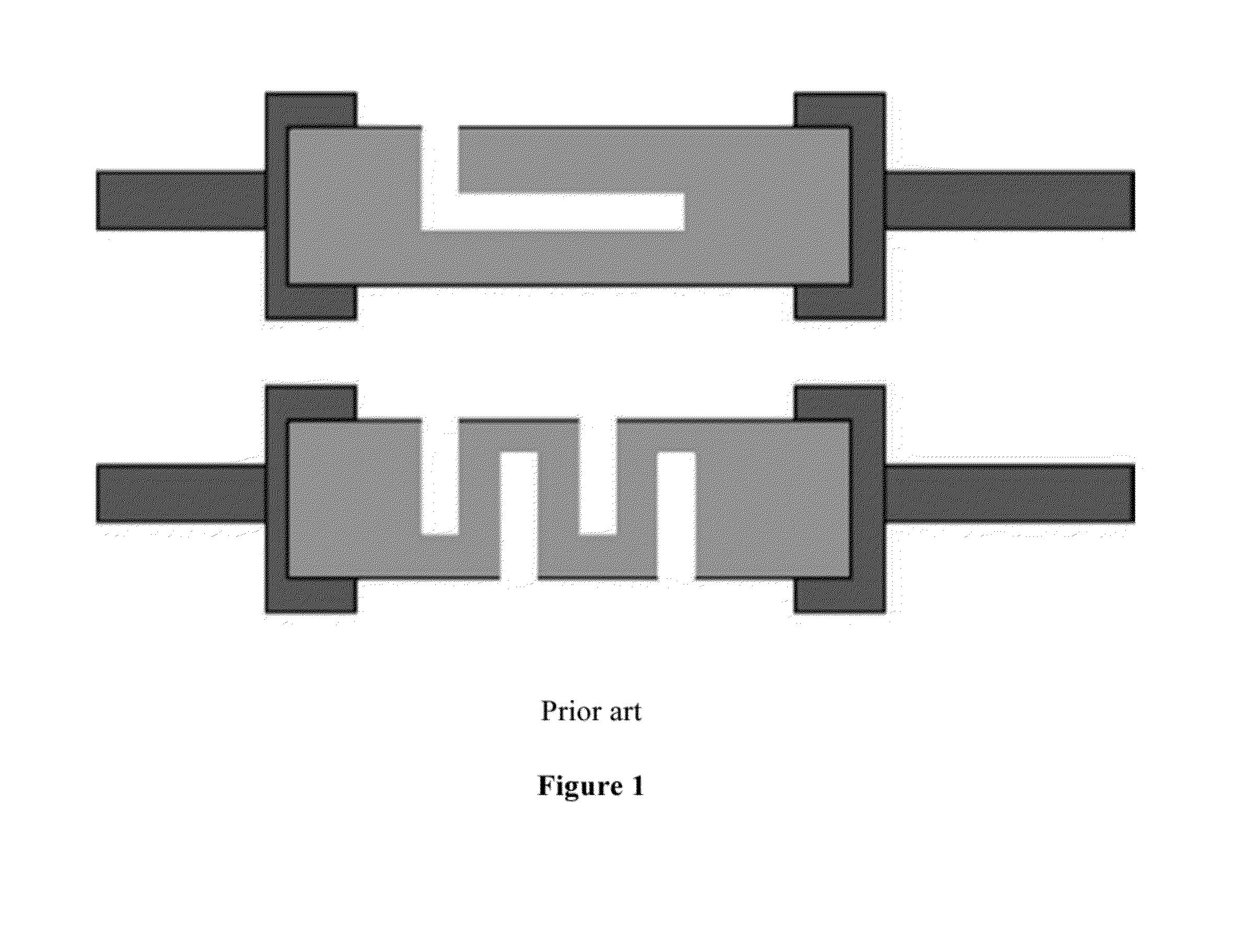
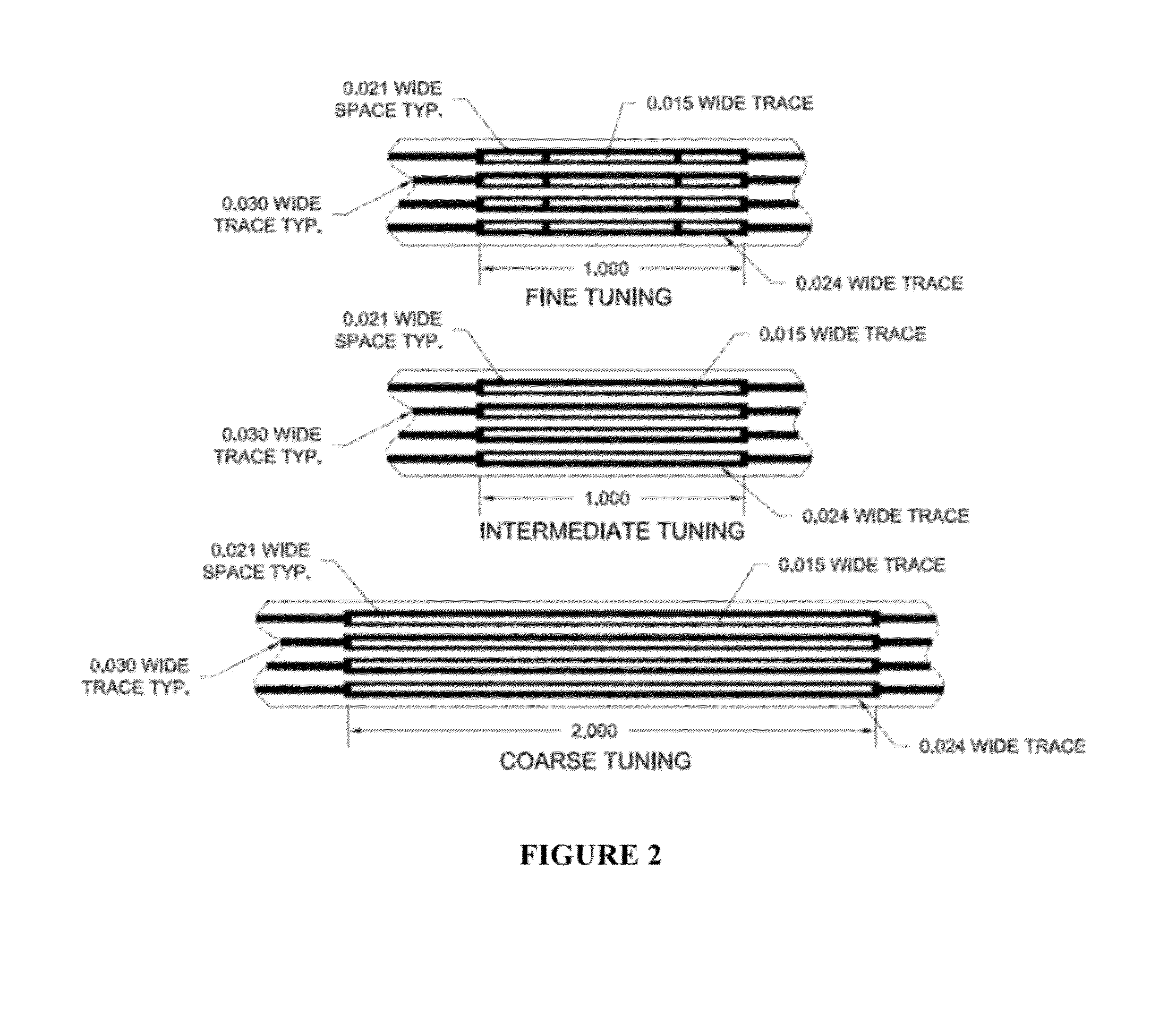
[0043]This invention solves the previously stated problems by adding multiple “tuning” sections made up of one or more closed conductive loops with multiple conductive paths on each conductor which can be easily and inexpensively severed to adjust the individual conductor resistances after the application of the conductive ink to the substrate. By varying the length of the tuning sections by design, it is possible to provide different degrees of adjustment from coarse adjustment to fine adjustment. See FIG. 2 for some embodiments of the present invention.

[0044]One application of the method and system of high-resistance, multiple-conductor flat cables of the present invention is for use in monitoring a patient while the patient is in or near a MRI machine: The range of resistance needed to overcome inductive interference caused by the MRI machine is from about 50 kOhms to about 70 kOhms for a 6 foot cable. Generally, the resistance is from about 8 kOhms to about 12 kOhms per foot of ...


PUM

PropertyMeasurementUnit
lengthaaaaaaaaaa
lengthsaaaaaaaaaa
thickaaaaaaaaaa

Abstract

The method and system of high-resistance, multiple-conductor flat cables which contain integral tunable resistance sections suitable for fine tuning the resistance of a conductor to match the resistance of the conductors to one another within a specified target value. The method involves the design and creation of the high-resistance, multiple-conductor flat cables and the tuning of the resistance of the conductor.

Description

CROSS-REFERENCE TO RELATED APPLICATIONS[0001]This application claims the benefit of U.S. Provisional Application No. 61 / 445,862, filed Feb. 23, 2011.FIELD OF THE INVENTION[0002]This invention relates to the field of multiple-conductor flat cables. More particularly, this invention relates to tunable, high-resistance, multiple-conductor flat cables.BACKGROUND OF THE INVENTION[0003]There is a need for high-resistance, multiple-conductor cables for use in Magnetic Resonance Imaging (MRI) procedures to monitor a patient's vital signs. The extreme magnetic fields produced by the MRI machine can interact with the patient monitoring cable producing image artifacts which corrupt the MRI image. Image artifacts can be minimized or eliminated by using a cable with a high enough resistance so that it is not affected by induction currents generated by the magnetic field.[0004]Current manufacturing methods are capable of producing such cables using round wire and wire harness manufacturing techni...

Claims


Application Information

Patent Timeline
Patent Type & Authority Patents(United States)
IPC IPC(8): H01B7/00
CPCH01C17/245H01C17/14H01C17/24H01C17/02H01C17/242H01C3/06Y10T29/49082Y10T29/49004Y10T29/49087
Inventor BULMER, DOUGLAS R.ROBERTS, JONATHANMURPHY, DAVIS
Owner MIRACO
Why Eureka
Try Eureka