
Control system for an electric machine

a control system and electric machine technology, applied in the direction of multiple dynamo-electric motor speed regulation, multiple dynamo-motor starters, synchronous motors starters, etc., can solve problems affecting and achieve the effect of improving the performance of electric machines and high speed rang

Inactive Publication Date: 2014-02-11
DYSON TECH LTD
View PDF61 Cites 5 Cited by
  • Summary
  • Abstract
  • Description
  • Claims
  • Application Information

AI Technical Summary

Benefits of technology

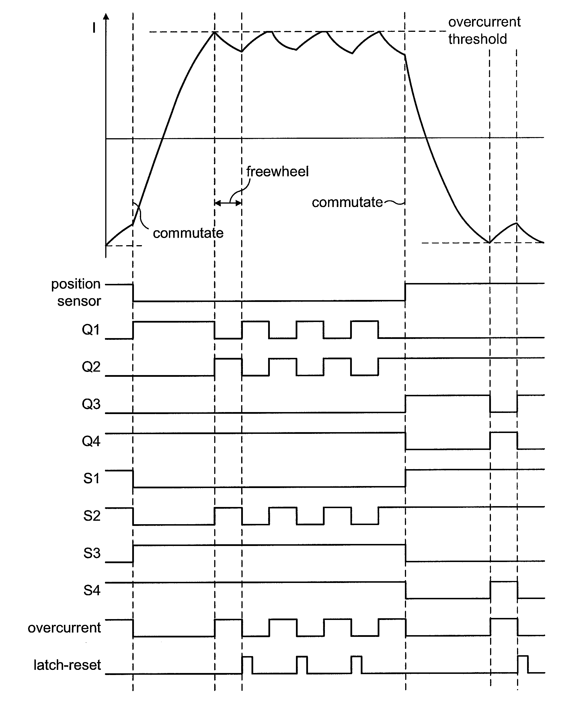
[0005]By employing a time window, spurious edges occurring outside the time window are ignored by the drive controller. As a result, the control system is less prone to electromagnetic noise, thus improving the performance of the electric machine.
[0007]The electric machine may have a first speed range (e.g. a low speed range) and a second speed range (e.g. a high speed range). When the electric machine operates within the first speed range, the drive controller generates control signals to excite the winding in synchrony with each edge of the signal and then ignores the signal for a predetermined time following generation of the control signals. Accordingly, any spurious edges in the signal that occur immediately after excitation are ignored by the drive controller and thus performance of the electric machine is improved. When the electric machine operates within the second speed range, the drive controller generates control signals in response to edges of the signal occurring within the time window. Accordingly, the drive controller employs two different schemes for minimising the detection of spurious edges, the two schemes depending on the speed of the electric machine.

Problems solved by technology

However, noise in the output signal may cause the phase to be excited at incorrect times, thus adversely affecting the performance of the electric machine.

Method used


Image

  • Control system for an electric machine
  • Control system for an electric machine
  • Control system for an electric machine

Examples


Embodiment Construction

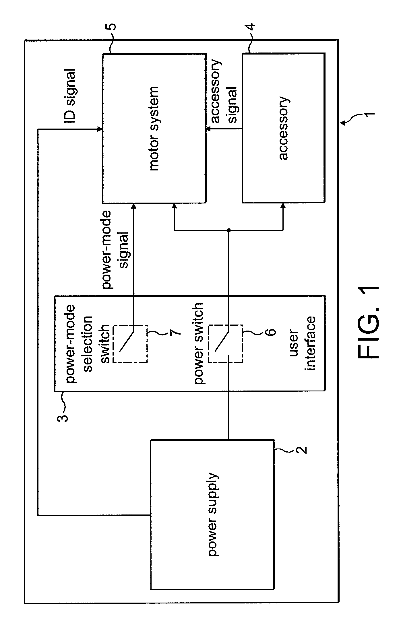
[0023]The product 1 of FIG. 1 comprises a power supply 2, a user interface 3, an accessory 4, and a motor system 5.

[0024]The power supply 2 comprises a battery pack that supplies a DC voltage to both the accessory 4 and the motor system 5. The power supply 2 is removable from the product 1 such that the product 1 may be used with different battery packs. For the purposes of the present description, the power supply 2 is either a 4-cell battery pack providing a 16.4 V DC supply or 6-cell battery pack providing a 24.6 V DC supply. In addition to providing a supply voltage, the power supply outputs an identification signal that is unique to the type of battery pack. The ID signal takes the form of a square-wave signal having a frequency that varies according to the type of battery pack. In the present example, the 4-cell battery pack outputs an ID signal having a frequency of 25 Hz (20 ms pulse length), while the 6-cell battery pack outputs an ID signal having a frequency of 50 Hz (10 ...


PUM


Abstract

A control system for an electric machine, the control system including a position sensor and a drive controller. The drive controller generates one or more control signals for exciting a winding of the electric machine in response to edges of a signal output by the position sensor. Moreover, the drive controller generates control signals in response to an edge that occurs within a time window. The time window starts at a time when control signals are generated and has a length less than the electrical half-cycle period.

Description

REFERENCE TO RELATED APPLICATIONS[0001]This application claims the priority of United Kingdom Application No. 0905878.5, filed Apr. 4, 2009, the entire contents of which are incorporated herein by reference.FIELD OF THE INVENTION[0002]The present invention relates to a control system for an electric machine.BACKGROUND OF THE INVENTION[0003]The output power of an electric machine is critically dependant on accurate synchronisation of phase excitation and rotor position. Accordingly, the electric machine typically includes a position sensor for determining the position of the rotor. The position sensor outputs a signal which is then used to control the timing of phase excitation. However, noise in the output signal may cause the phase to be excited at incorrect times, thus adversely affecting the performance of the electric machine.SUMMARY OF THE INVENTION[0004]In a first aspect, the present invention provides a control system for an electric machine, the control system comprising a p...

Claims


Application Information

Patent Timeline
Patent Type & Authority Patents(United States)
IPC IPC(8): H02P5/00
CPCH02P6/16H02P6/14H02P27/08H02K29/08H02P6/17
Inventor DAI, HANPING
Owner DYSON TECH LTD
Learn More