
Structure of loudspeaker for reducing thickness and mounting depth

a loudspeaker and structure technology, applied in the field of loudspeakers, to achieve the effect of reducing the thickness or height of the speaker and reducing the depth

Inactive Publication Date: 2011-10-06
ALPINE ELECTRONICS INC
View PDF3 Cites 13 Cited by
  • Summary
  • Abstract
  • Description
  • Claims
  • Application Information

AI Technical Summary

Benefits of technology

It is an object of the present invention to provide a structure of a loudspeaker to decrease a thickness or height thereof, thereby reducing a depth for mounting the loudspeaker on a panel or wall.
It is another object of the present invention to provide a structure of a loudspeaker to reduce the mounting depth of the loudspeaker while maintaining a high excursion performance of the loudspeaker.
It is a further object of the present invention to provide a novel design to remove mechanical clearance of the loudspeaker by allowing the spider to pass through cut-outs formed on a magnetic assembly.
It is a further object of the present invention to provide a structure of the loudspeaker in which a spider is allowed to be placed further away from the diaphragm to improve axial stability so that the loudspeaker is less prone to “rocking” which may affect the loudspeaker's sensitivity and reliability.
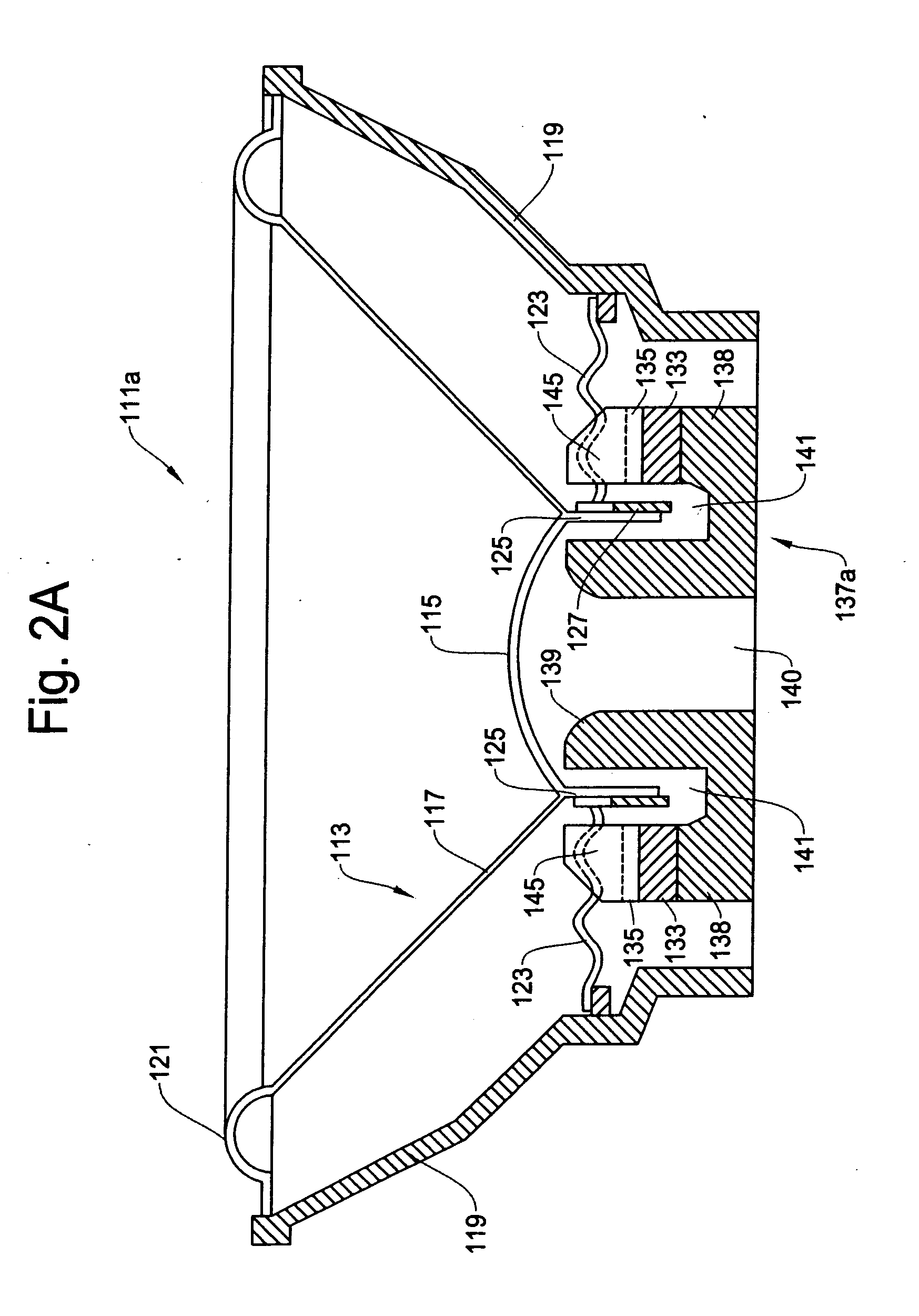
In the loudspeaker of the present invention, the diaphragm includes diaphragm frames which are aligned with the suspension elements of the spider close to one another so that both the diaphragm frames and the suspension elements are inserted in the cut-outs on the magnetic assembly when assembled, thereby increasing mechanical strength of the diaphragm.
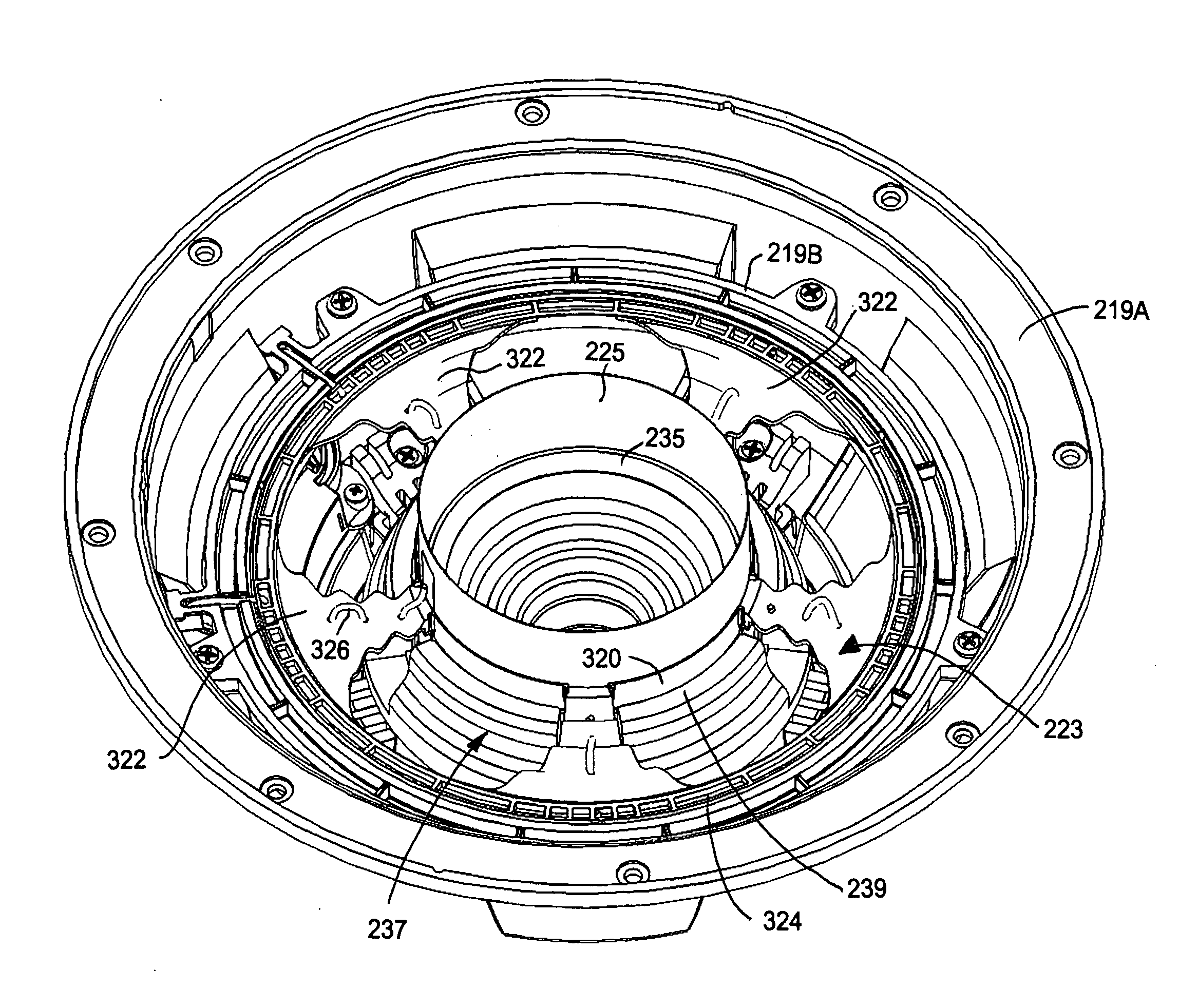
According to the present invention, on the top of the magnetic assembly, a plurality of cut-outs (magnetic gap) are provided to receive corresponding suspension elements of the spider. Thus, each of the suspension elements can be inserted in an inside space of the cut-out when the loudspeaker is assembled, which makes it possible to dramatically reduce the distance between the diaphragm and the magnetic assembly. Consequently, it is possible to dramatically reduce the vertical length of the coil bobbin, thereby dramatically reducing the thickness, i.e., mounting depth, of the loudspeaker. The basic concept of the present invention can be applied to a variety of loudspeakers, ranging from mid-range, coaxial speakers, all the way to high-excursion subwoofers.

Problems solved by technology

The need for shallow, low profile speakers are not only limited to home audio use, but also in cars, boats, airplanes and other locations that will benefit from the depth reduction without suffering a sound quality and pressure level.

Method used


Image

  • Structure of loudspeaker for reducing thickness and mounting depth
  • Structure of loudspeaker for reducing thickness and mounting depth
  • Structure of loudspeaker for reducing thickness and mounting depth

Examples


Embodiment Construction

The detailed description set forth below is intended as a description of the presently exemplary device provided in accordance with aspects of the present invention and is not intended to represent the only forms in which the present invention may be prepared or utilized. It is to be understood, rather, that the same or equivalent functions and components may be accomplished by different embodiments that are also intended to be encompassed within the spirit and scope of the invention.

Unless defined otherwise, all technical and scientific terms used herein have the same meaning as commonly understood to one of ordinary skill in the art to which this invention belongs. Although any methods, devices and materials similar or equivalent to those described can be used in the practice or testing of the invention, the exemplary methods, devices and materials are now described.

All publications mentioned are incorporated by reference for the purpose of describing and disclosing, for example, ...


PUM


Abstract

A structure of a loudspeaker is designed to decrease a thickness or height thereof, thereby reducing a mounting depth of the loudspeaker on a mounting panel or wall. The loudspeaker includes a speaker frame, a diaphragm connected to the speaker frame in a manner capable of vibration, a voice coil connected to the diaphragm through a coil bobbin to receive an electric signal to vibrate the diaphragm, a spider connected to the speaker frame and to the diaphragm for supporting the diaphragm and the voice coil in a flexible manner, a magnetic assembly including a top plate, a permanent magnet and a pole piece for creating a magnetic circuit for interaction with the voice coil inserted in an air gap, and a plurality of cut-outs formed on a top of the magnetic assembly at an outside thereof to receive therein corresponding suspension elements of the spider.

Description

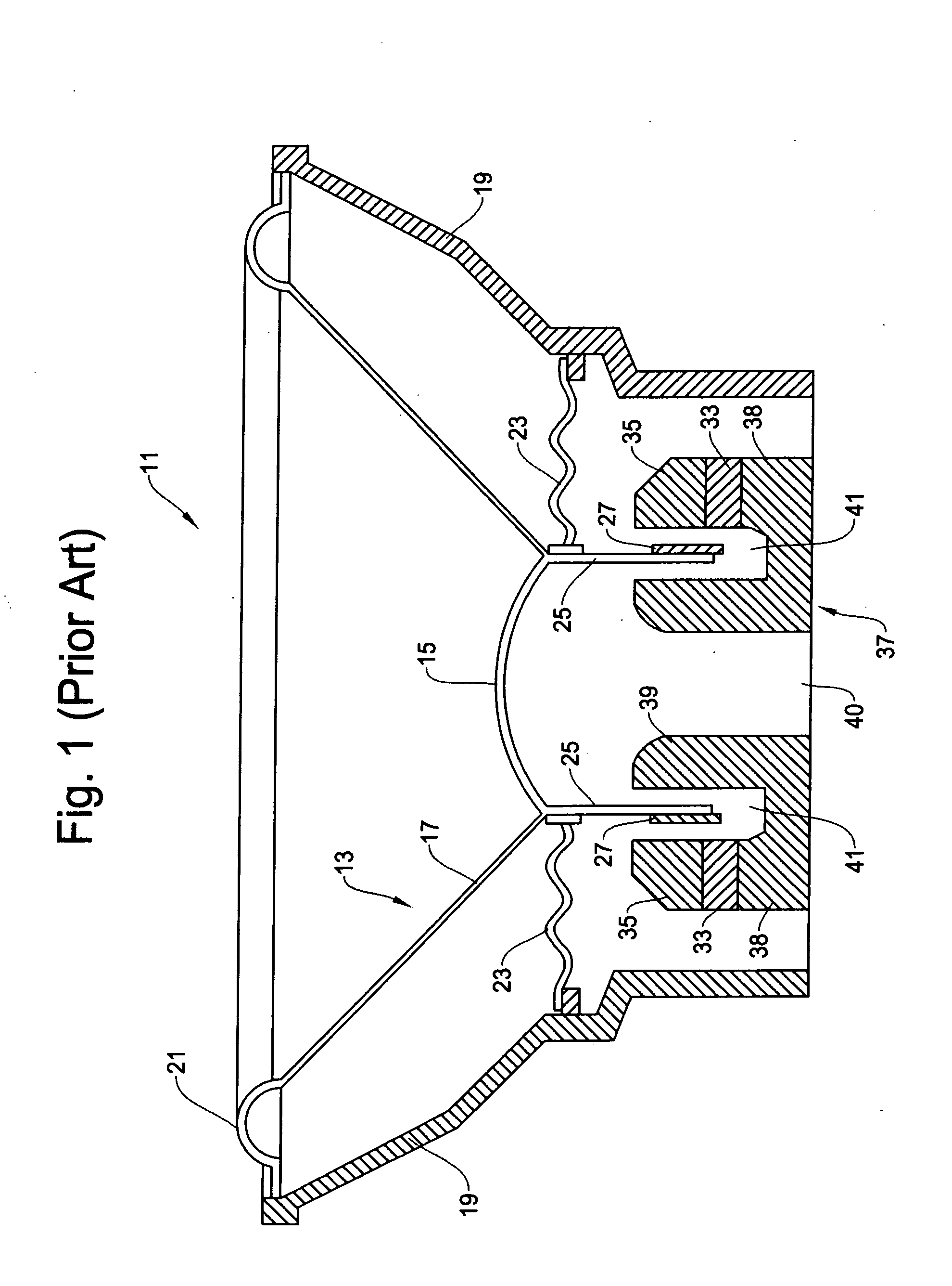
FIELD OF THE INVENTIONThis invention relates to a loudspeaker, and more particularly, to a structure of a loudspeaker to decrease a thickness or height thereof, thereby reducing a depth for mounting the loudspeaker on a panel or wall.BACKGROUND OF THE INVENTIONLoudspeakers are well known in the art and are commonly used in a variety of applications, such as in home theater stereo systems, car audio systems, indoor and outdoor concert halls, and the like. Those who want to enjoy a very large volume of sound produced by such a car audio system typically mount several loudspeakers in the car to enjoy the large sound when driving the car. A loudspeaker includes an acoustic transducer comprised of an electro-mechanical device which converts an electrical signal into acoustical energy in the form of sound waves and an enclosure for directing the sound waves produced upon application of the electrical signal.An example of structure in the conventional loudspeaker is shown in FIG. 1. As sho...

Claims


Application Information

Patent Timeline
Patent Type & Authority Applications(United States)
IPC IPC(8): H04R1/00
CPCH04R9/043H04R9/025
Inventor WALTER, JAMES J.
Owner ALPINE ELECTRONICS INC
Learn More