
Hybrid hydro (air) static multi-recess journal bearing

a static journal bearing and hydrostatic journal technology, applied in the direction of bearings, shafts and bearings, rotary bearings, etc., can solve the problems of increasing the heat generation of the bearing in operation, the bearing type cannot be applied to high speed use, and the bearing type has relatively low stiffness and a low damping ratio, so as to reduce friction power, high speed, and simple manufacturing

Inactive Publication Date: 2014-02-11
ELKA PRECISION
View PDF21 Cites 10 Cited by
  • Summary
  • Abstract
  • Description
  • Claims
  • Application Information

AI Technical Summary

Benefits of technology

The invention provides multi-recess hydrostatic journal bearings that combine hydrostatic and hydrodynamic forces, have reduced friction power at high speeds, better thermal stability, and do not contain additional moving parts. The recesses have inclined surfaces that generate additional hydrodynamic forces, increase stiffness and load capacity, reduce friction power, and improve thermal stability. The bearing housing has a bushing made of a porous material mounted inside it, with an annular slot and openings for a pump. The shaft rotates inside the bushing and is separated from its inner surface by a layer of pressurized liquid media. The inclined surfaces on the bushing have inclined portions that form gaps with the outer surface of the shaft, which also generate additional hydrodynamic forces.

Problems solved by technology

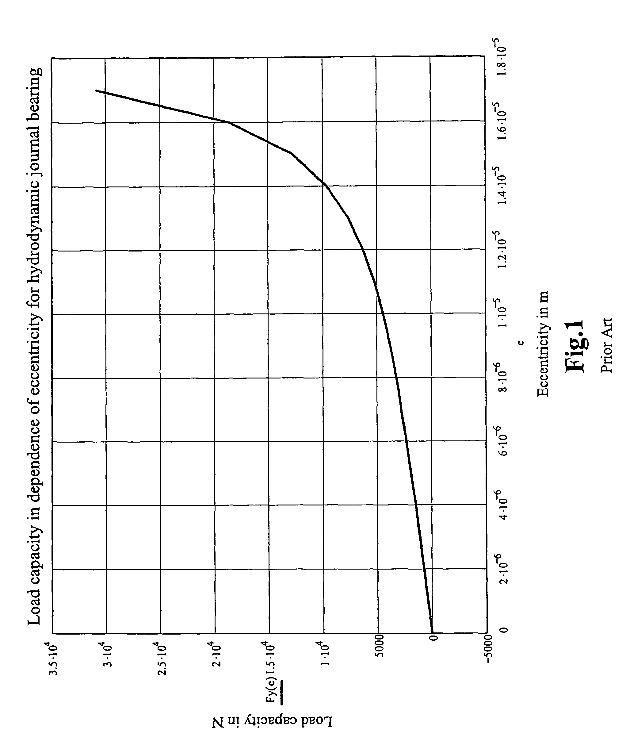
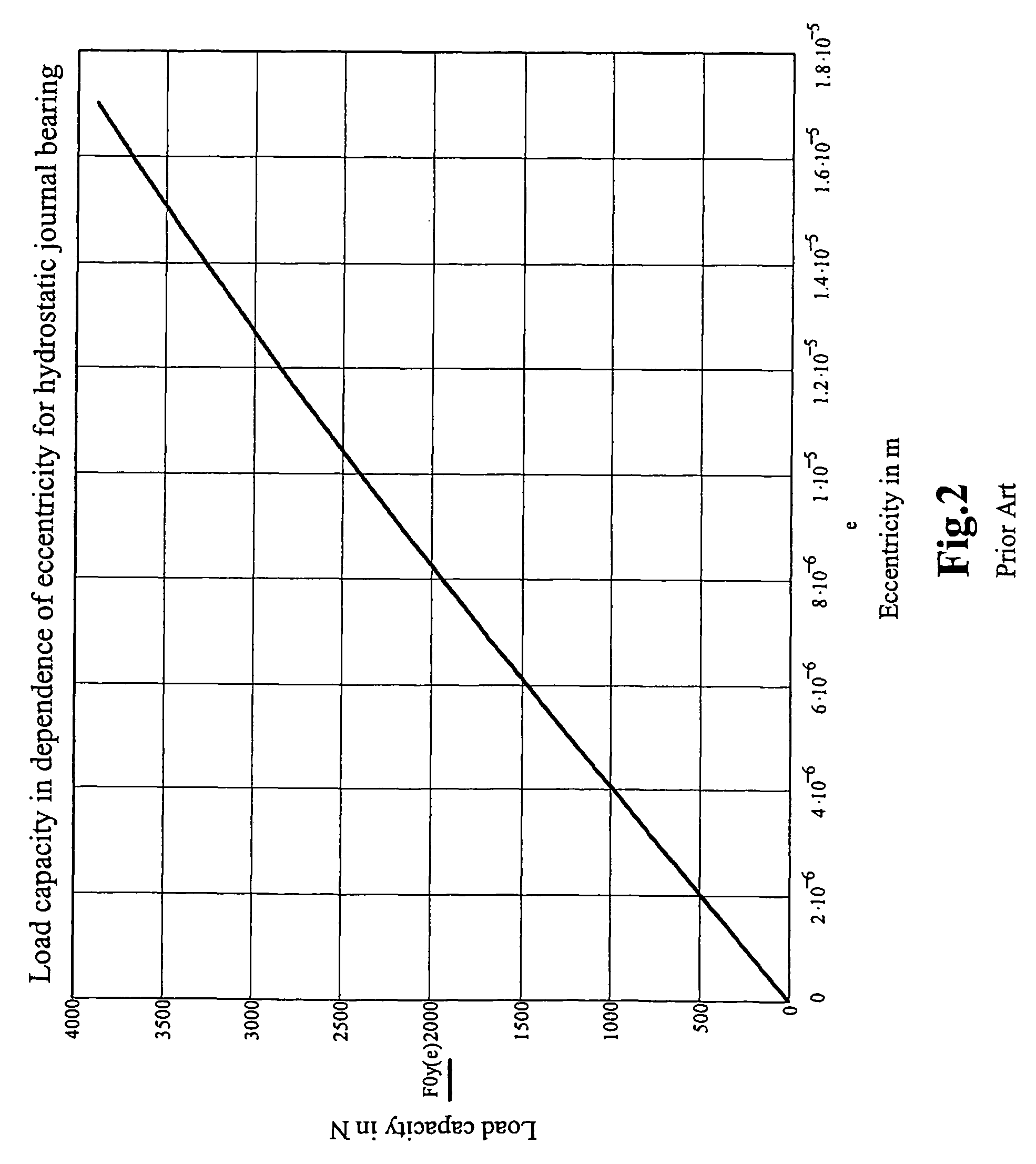
However, this type of bearing has relatively low stiffness and a low damping ratio, about 5 to 8 times lower compared with the same size multi-recess bearing having inlet restrictors.
A problem of this type of bearing is that the additional artificially created space, e.g., land portions 17, increases the heat generation of the bearing in operation.
This type of bearing can not be applied to high speed use because of significantly increased friction in operation due to the significantly increased gap area inherent in this design.
However, this type of bearing suffers from the problem of being much more sophisticated and much more expensive to manufacture than conventional bearings, and stiffness in the central position is not high because of the flexibility of the pivoting pads.
Additionally, this type of bearing suffers from the problem that the pads and an elastomeric bushing reduce rotational accuracy.
However, in contrast to variations of the bearings disclosed herein, this type of bearing is not suitable for applications requiring high central stiffness and high rotational precision, such as precision machining applications, because stiffness in the central position and rotational accuracy are the most critical characteristics for machine tool spindles, especially for grinding machines.
In vertical orientations, the problem of fluid leakage is extremely critical.
However, this type of bearing suffers from the problem that this design almost completely eliminates the advantages of hydrodynamic effects because, in operation, pressure will increase in the converged portion of the gap but will decrease in the diverged portion of the gap.
Further, this type of bearing suffers from the problem that cavities (areas with negative pressure) can form in operation, which can be very dangerous to the spindle's stability.
In general, these bearings do little to increase the hydrodynamic component of the stiffness over conventional bearings.
During operation, the gaps generate additional hydrodynamic forces and increase stiffness and load capacity of the bearing.

Method used


Image

  • Hybrid hydro (air) static multi-recess journal bearing
  • Hybrid hydro (air) static multi-recess journal bearing
  • Hybrid hydro (air) static multi-recess journal bearing

Examples


first embodiment

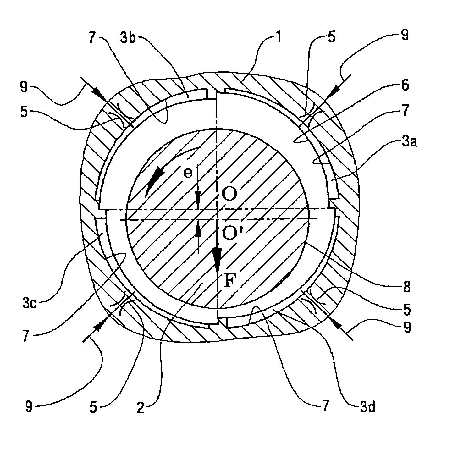
[0034]FIGS. 5-6 show a bearing having a bearing housing 1. FIG. 5 shows an isometric view of a bearing showing a recess 3 and FIG. 6 shows a cross-sectional view of the bearing in a plane perpendicular to both the rotational axis O′ of a shaft 2 and the geometrical axis O of the bearing housing 1 opening. When the axis O′ of shaft 2 and the geometrical axis O of bearing housing 1 coincide, the shaft 2 is in the central position. In this embodiment, as shown in FIG. 6, shaft 2 rotates in the direction shown by the arrow. Bearing housing 1 has four recesses 3a-3d. The four recesses 3a-3d are shown for descriptive purposes only. The actual number of recesses can be any number equal to or greater than three. Each recess 3a-3d has a surface 7 defining the bottom of the recess 3. The inclined surfaces 7 each creates a variable gap between the surface 7 and the outer surface of the shaft 2. That is, if the shaft 2 is in the central position, the gap areas defined between the surfaces 7 of ...

third embodiment

[0041]FIGS. 8-9 show a In this embodiment, each recess in the hydrostatic journal bearing contains an island 100 in the middle of the recess 3. Each island 100 is surrounded by a corresponding one of grooves 10a-10d. Each island 100 includes an elevated and inclined surface 11 that forms a variable gap with the outer surface of the shaft 2. That is, if the shaft 2 is in the central position, the gap areas defined between the surfaces 11 of the islands 100 and the outer surface of shaft 2 have widths, as measured along the radial direction from the axis O of the bearing housing 1, that decrease in the direction of rotation of the shaft 2. The variable gaps defined by the islands 100 and the shaft 2 generate hydrodynamic forces. For every recess, oil (represent by the arrow 9) is supplied from an external hydraulic power unit through the inlet restrictors 5 to a groove surrounding the said elevated internal portion of the recess.

[0042]From the pump of the external hydraulic power uni...


PUM


Abstract

Multi-recess hydrostatic journal bearings support a rotating shaft and have inclined surfaces, each inclined surface forming a variable radial gap with the surface of the shaft, the variable gaps converging in the direction of rotation of the shaft to increase hydrodynamic forces, reduce a turbulent component of shear friction, and improve the thermal stability of the journal bearing. The inclined surfaces can be formed in one or more of portions of recess bottoms in recesses, portions of gap lands surrounding recesses, and portions of an inner surface of a bushing.

Description

INCORPORATION BY REFERENCE[0001]This application claims the benefit of U.S. Provisional Application No. 60 / 960,064, “HYBRID HYDRO (AIR) STATIC MULTI-RECESS JOURNAL BEARING” filed on Sep. 13, 2007, which is incorporated herein by reference in its entirety.BACKGROUND[0002]Hydrostatic journal and thrust bearings supporting hydrostatic spindles are widely used in many different applications ranging from precision machine tools to turbomachinery. Hydrostatic bearings have the characteristics of ultra-high rotational accuracy, high static stiffness, extremely high resistance to vibrations, extremely high stability, and being virtually free of wear. The thermal stability of hydrostatic bearings is also very high because the circulating liquid media, e.g. oil, flow through the hydrostatic bearings from an external hydraulic power unit usually has precise temperature control. Further, the almost equal thermal expansion of the rotating shaft and the bearing housing of hydrostatic bearings kee...

Claims


Application Information

Patent Timeline
Patent Type & Authority Patents(United States)
IPC IPC(8): F16C32/06
CPCF16C32/06F16C33/1075F16C17/028F16C32/0685
Inventor KASHCHENEVSKY, LEONID
Owner ELKA PRECISION
Learn More