Turbine shroud
a technology for turbines and shrouds, applied in the direction of machines/engines, liquid fuel engines, lighting and heating apparatus, etc., can solve the problems of affecting the performance of gas turbine engines, serious fuel economy problems, engine performance drop, etc., and achieve the effect of reducing the thermal stress of each shroud segmen
- Summary
- Abstract
- Description
- Claims
- Application Information
AI Technical Summary
Benefits of technology
Problems solved by technology
Method used
Image
Examples
second embodiment
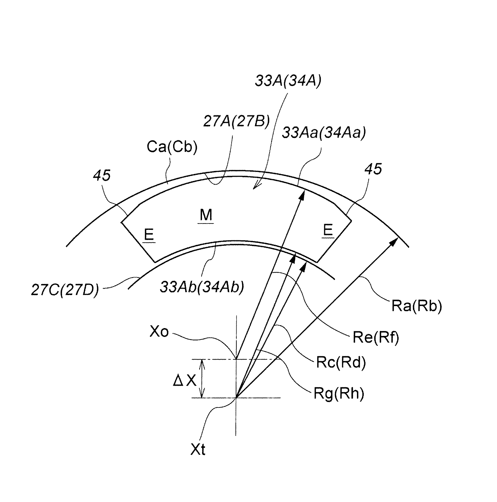
[0063]FIG. 9 shows the present invention. In this embodiment, the inner circumferential surfaces 27A and 27B of the annular axial slots 51 and 52 of the turbine casing 27 opposing the outer circumferential surfaces 33Aa and 34Aa of the front and rear axial walls 33A and 34A, respectively, are defined by cylindrical surfaces centered around the rotational center Xt of the turbine and having radii of Ra and Rb, respectively, and the outer circumferential surfaces 33Aa and 34Aa of the axial walls 33A and 34A are defined by non-cylindrical surfaces such as elliptic and parabolic surfaces that define a greater clearance in each circumferential end than in the circumferential middle part. The outer circumferential surfaces of the axial walls are each additionally formed with a planar sloping surface 45 at each circumferential end thereof.
[0064]In this case also, when the surrounding temperature is low, the clearance is greater in each circumferentially terminal end than in the circumferen...
third embodiment
[0066]FIGS. 10A and 10B show the present invention. In particular, FIG. 10A shows the state of a shroud segment 31 when the engine is cold, and FIG. 10B shows the state of the shroud segment 31 when the engine is warmed up. The shroud segment 31 is configured such that, when the engine is cold, the clearance Cc, Cd between the inner circumferential surface 33Ab, 34Ab of each axial wall 33A, 34A and opposing outer circumferential surface 27C, 27D of the annular axial slot 51, 52 is greater in a circumferential middle part M thereof than each circumferential end part thereof E.
[0067]In this case, whereas the outer circumferential surface 33Aa, 34Aa of each axial wall 33A, 34A consists of a cylindrical surface centered around the rotation center Xt of the turbines, the inner circumferential surface 33Ab, 34Ab of the axial wall 33A, 34A is centered around an axial center offset from the rotation center Xt of the turbines, and is given with a smaller curvature radius. The outer circumfer...
fourth embodiment
[0070]FIGS. 11A and 11B show the present invention. In particular, FIG. 11A shows the state of a shroud segment 31 when the engine is cold, and FIG. 11B shows the state of the shroud segment 31 when the engine is warmed up. The shroud segment 31 is configured such that, when the engine is cold, the clearance Cc, Cd between the inner circumferential surface 33Ab, 34Ab of each axial wall 33A, 34A and opposing outer circumferential surface 27C, 27D of the annular axial slot 51, 52 is greater in a circumferential middle part M thereof than in each circumferential end part thereof E, and, additionally, the clearance Ca, Cb between the outer circumferential surface 33Aa, 34Aa of each axial wall 33A, 34A and opposing inner circumferential surface 27A, 27B of the annular axial slot 51, 52 is greater in each circumferential end part thereof E than in a circumferential middle part M thereof.
[0071]In this case also, when the engine is warmed up, the thermal deformation of the shroud segment 31...
PUM
 Abstract
Description
Claims
Application Information
 - R&D
- Intellectual Property
- Life Sciences
- Materials
- Tech Scout
- Unparalleled Data Quality
- Higher Quality Content
- 60% Fewer Hallucinations
Browse by: Latest US Patents, China's latest patents, Technical Efficacy Thesaurus, Application Domain, Technology Topic, Popular Technical Reports.
© 2025 PatSnap. All rights reserved.Legal|Privacy policy|Modern Slavery Act Transparency Statement|Sitemap|About US| Contact US: help@patsnap.com


