
Cantilever beam structural resonant-type integrated optical waveguide accelerometer

a technology of integrated optical waveguide and cantilever beam, which is applied in the direction of acceleration measurement using interia forces, instruments, optical elements, etc., can solve the problems of large size, severe degradation of detection sensitivity of the device, and low detection sensitivity, and achieves low cost, high stability, and small size

Active Publication Date: 2014-02-04
SOUTHEAST UNIV
View PDF19 Cites 5 Cited by
  • Summary
  • Abstract
  • Description
  • Claims
  • Application Information

AI Technical Summary

Benefits of technology

The present invention provides an accelerometer that uses integrated optical device processing technologies and organic polymer optical waveguide structures that are insensitive to temperature fluctuations. The key technical parameters of the accelerometer can be adjusted in a wide range and the device has advantages such as small size, light weight, high stability, simple production process, can be produced by mass production, and can reduce costs significantly. The detection principle of the accelerometer is different from existing technologies, as it detects acceleration by measuring the change of optical intensity at the resonant frequency and the phase difference of optical signals resulting from acceleration, resulting in higher detection sensitivity and insusceptibility to environmental temperature fluctuations and double refraction of waveguides.

Problems solved by technology

A main drawback of such accelerometers is if the phase difference between the two optical signals is small, then the change of optical intensity is not obvious, and therefore the detection sensitivity is not high.
However, due to the effect of environmental temperature fluctuations and double refraction of waveguide, the resonant spectral lines have horizontal displacement and asymmetrical distribution, which result in severe degradation of detection sensitivity of the device.
According to the system constitution of elements and devices, the optical sensing elements and optical transmission path of existing optical accelerometers are mainly composed of discrete devices such as optical fiber, optical grating, fiber grating, reflector, etc., which have large size, high production cost, and poor system stability, etc.

Method used


Image

  • Cantilever beam structural resonant-type integrated optical waveguide accelerometer
  • Cantilever beam structural resonant-type integrated optical waveguide accelerometer
  • Cantilever beam structural resonant-type integrated optical waveguide accelerometer

Examples


Embodiment Construction

[0021]Hereinafter the technical solution of the present invention will be further described in conjunction with the accompanying drawings.

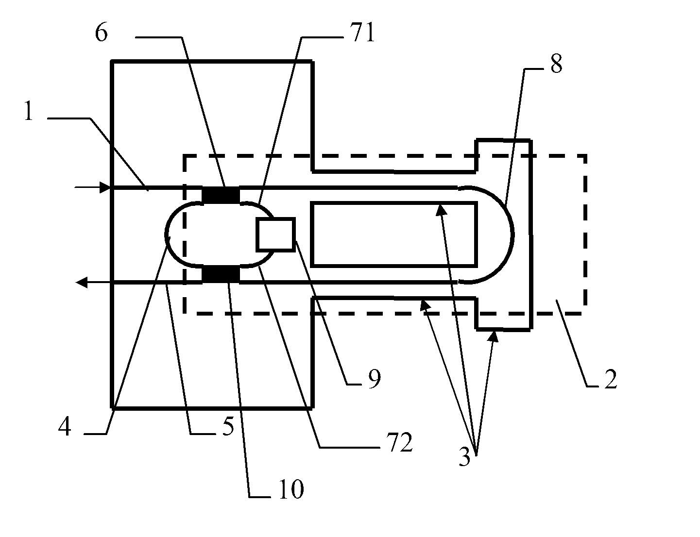
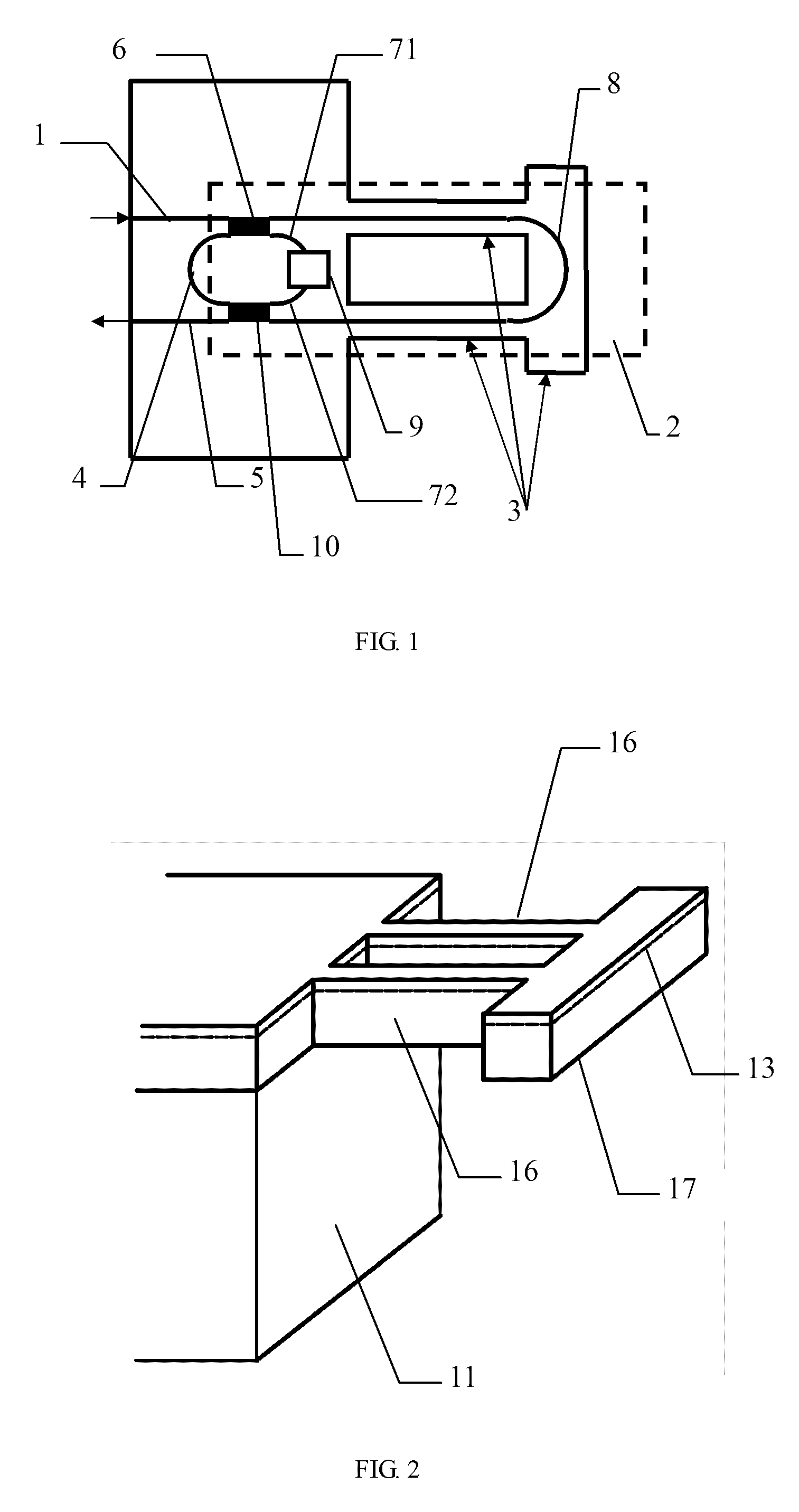
[0022]The structure of the cantilever beam structural resonant-type integrated optical waveguide accelerometer of the present invention is shown in FIG. 1. The optical signal channel comprises: an input waveguide 1, an asymmetric Mach-Zehnder interferometer 2, a short curved waveguide 4, an output waveguide 5, an asymmetric Mach-Zehnder interferometer 2, and a short curved waveguide 4, wherein, the asymmetric Mach-Zehnder interferometer 2 comprises a first 2×2-port directional coupler 6, a short waveguide 71, a phase modulator 9, a short waveguide 72, a long curved waveguide 8, and a second 2×2-port directional coupler 10. The input waveguide 1, short curved waveguide 4, output waveguide 5, first 2×2-port directional coupler 6, short waveguide 71, phase modulator 9, short waveguide 72, and second 2×2 port directional coupler 10 in the acceleromete...


PUM


Abstract

A cantilever beam structural resonant-type integrated optical waveguide accelerometer, includes an input waveguide (1), a dissymmetrical structural Mach-Zehnder interferometer (2), a micro-mechanical vibration cantilever beam (3), a short curved waveguide (4) and an output waveguide (5); all the waveguide structures and the cantilever beam use the integrated optical micromachining technique, and the device single-scale integration can be realized by using the temperature-insensitive organic polymer optical waveguide structure and the organic polymer substrate, the key technique indexes such as detection sensitivity, dynamic range are extensively adjusted. The phase difference of the optical signal can be measured by detecting the optical intensity of the resonant frequency of the optical circuit so as to achieve high sensitive acceleration detection, and to be free from the effect of the ambient temperature disturbance and waveguide birefringence.

Description

CROSS-REFERENCE TO RELATED APPLICATION(S)[0001]This application is a National Phase Patent Application and claims the priority to and benefit of International Application Number PCT / CN2009 / 074144, filed on Sep. 23, 2009, which claims priority of Chinese Patent Application Number 200910024475.3, filed on Feb. 23, 2009.FIELD OF THE INVENTION[0002]The present invention relates to the field of integrated optics and sense technology, particularly relates to a cantilever beam structural resonant-type integrated optical waveguide accelerometer, and more particularly relates to a monolithically integrated accelerometer with high sensitivity.BACKGROUND OF THE INVENTION[0003]An accelerometer is an important test component in inertial navigation, inertial guidance, and control testing devices. Both inertial navigation and inertial guidance utilizes the accelerometer's sensitivity to test the movement acceleration of the carrier. Nowadays, accelerometers are widely applied to aviation, navigati...

Claims


Application Information

Patent Timeline
Patent Type & Authority Patents(United States)
IPC IPC(8): G01P15/08
CPCG02B6/12007G01P15/097G02B2006/12138G02B6/1221G01P15/093
Inventor ZHANG, TONGXUE, XIAOJUNZHANG, XIAOYANGWU, PENGQIN
Owner SOUTHEAST UNIV
Learn More