
Feeding system for an inductive load from an energy source with variable power

Inactive Publication Date: 2014-01-28
IND DE MOTORES ANAUGER
View PDF12 Cites 0 Cited by
  • Summary
  • Abstract
  • Description
  • Claims
  • Application Information

AI Technical Summary

Benefits of technology

The patent describes a system that efficiently converts the electric power from a continuous current source into alternating current. This is done without using batteries, reducing maintenance and allowing for larger power generation. The system uses a digital micro controller to optimize operation parameters and is protected from damage by a low energy loss switch. Overall, this results in improved performance for the inductive load.

Problems solved by technology

In particular, the larger the system hydraulics pressure, the larger the need of energy for the motor to reach a minimum rotation.
To eliminate or to reduce such effects, they usually employ great quantities of solar cells or larger aeolic power generation, which increases the systems implantation cost.
However, the cost involved with this solution makes it completely unfeasible.
These systems operate in analogous form, where the circuit signals are treated in direct form, not allowing attending to the variables to which the system is subject, without alterations in the electronic project; this carries circuit costs increase, it limits the system input power, does not allow the use of higher performance pumps and does not allow its use in aeolic generators, due to the high power supplied by these devices.
The use of such techniques reduces the system revenue, increasing the installed power cost of solar cells by pumped liter.
Further, the protection means for the circuit are onerous and inefficient, operating only with independent systems.

Method used


Image

  • Feeding system for an inductive load from an energy source with variable power
  • Feeding system for an inductive load from an energy source with variable power
  • Feeding system for an inductive load from an energy source with variable power

Examples


Embodiment Construction

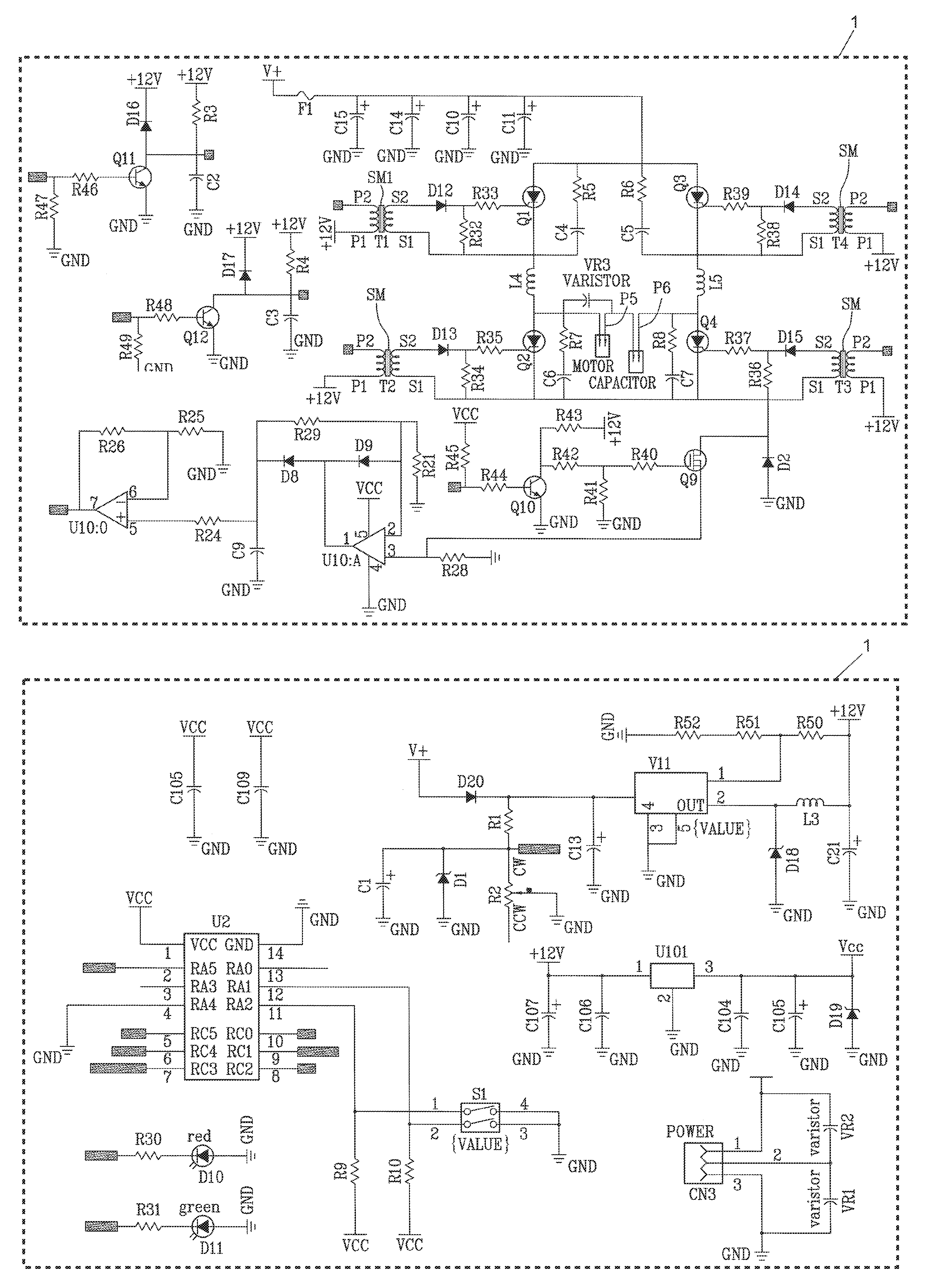
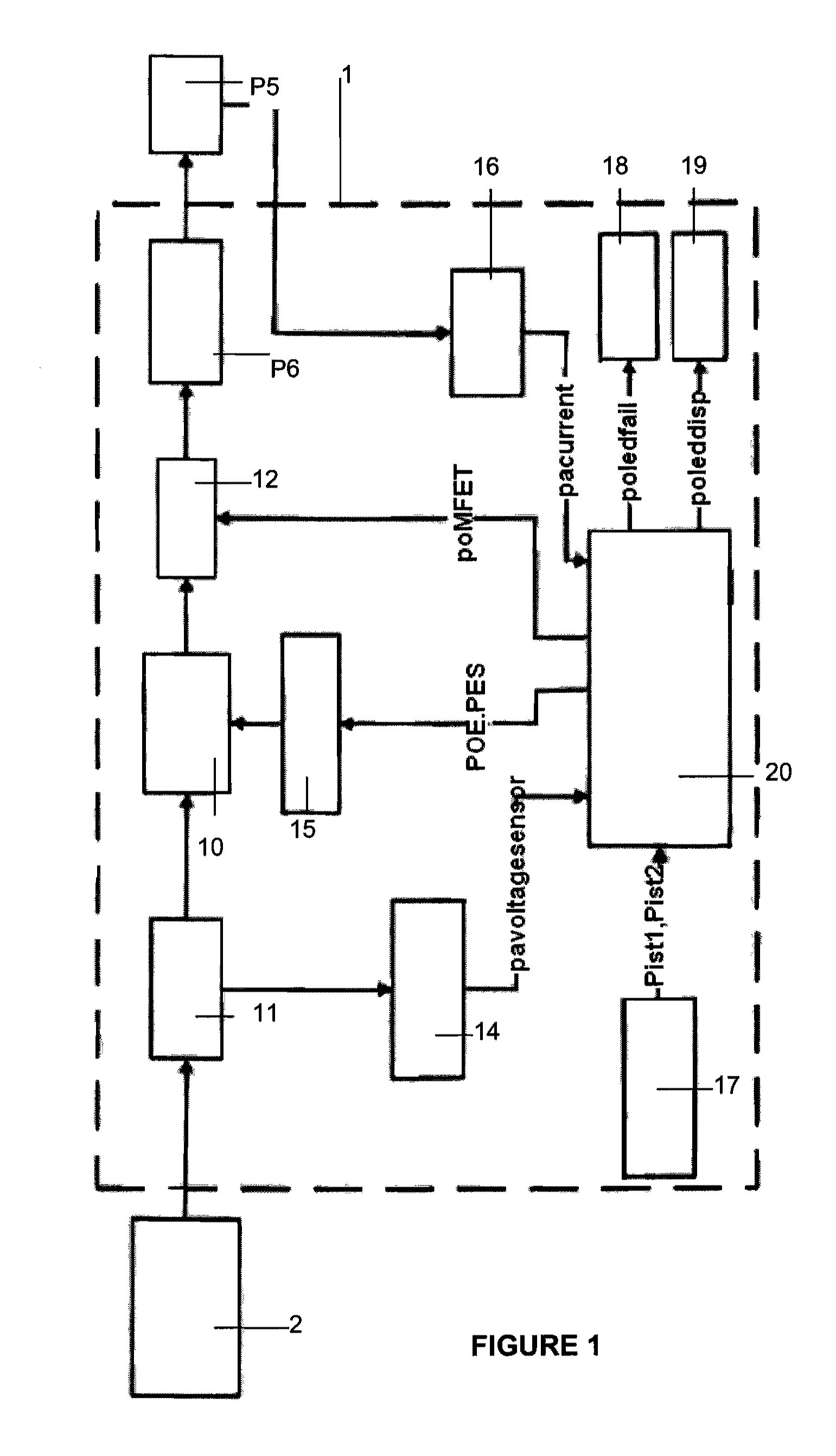
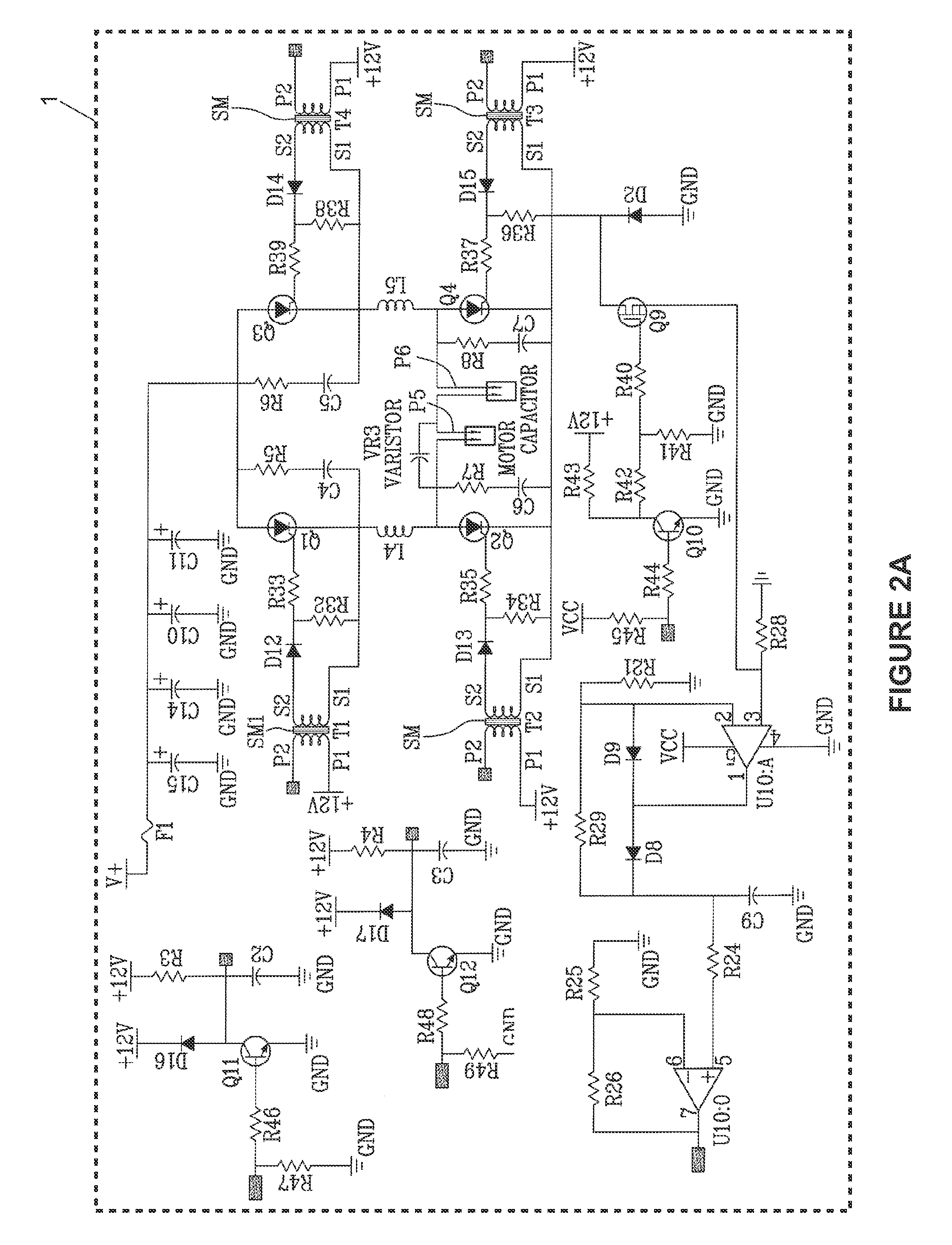
[0013]In a succinct form, the present invention concept is based on electric power transformation of continuous current generated by an energy source, in pulses, through a digital technique, that results in a larger control, with consequent low maintenance and system larger efficiency. The electric power conversion of continuous current supplied by the source is accomplished through a resonant RCL series circuit, which is formed by a capacitor (P6) associate to the coil of inductive load (P5).

[0014]For a better comprehension of the concepts that govern the present invention, described below is one of the possible forms of carrying out the invention, in which the energy source is represented by a bank of solar cells, while the inductive load is represented by a vibratory pump, this pump configured for the pumping of water. Nevertheless the illustrative scope and not limiting of this accomplishment, the experts in the art are going to realize that the concepts and the materialization ...


PUM


Abstract

A system is provided for the feeding of an inductive load, with electric power of continuous current, generated from an energy source and, more in particular, to a feeding system for a vibratory pump from solar or aeolic energy, which processes the electric power of continuous current supplied by a bank of solar cells or aeolic generator, in a compatible form, using a circuit of electronic command by digital micro controller, for the control and actuation of vibratory pump, independent of the electric power variations supplied by the sources as solar cells, due to the alterations in the level of solar radiation; or in aeolic generator, due to wind speed variations.

Description

FIELD OF THE INVENTION[0001]The present invention refers to a system for feeding of an inductive load starting from an energy source whose net power varies regarding time.[0002]Preferably, the present invention refers to a vibratory pump with electric power feeding of continuous current, generated by a bank of solar cells or an aeolic generator. More in particular, a feeding system for a vibratory pump starting from solar or aeolic energy is described, which processes the electric energy of continuous current supplied by the bank of solar cells or aeolic generator, in compatible form, using an electronic circuit of command by digital micro-controller, for the control and the activation of the vibratory pump, independent of electric power variations supplied by the source, due to the alterations in the level of solar radiation or due to wind speed variations.BACKGROUND[0003]It is known that the systems that use pumps activated from a motor of continuous current have the need to gener...

Claims


Application Information

Patent Timeline
IPC IPC(8): F04B17/03H02M7/5383F04B49/06
CPCH02M2001/0022H02J3/386Y02E10/563H02M2007/4815H02J3/383H02M7/537Y02E10/763Y02B70/1441H02M2003/1555H02J3/382H02J2300/28H02J2300/20H02J2300/24H02J3/381Y02B70/10Y02E10/56Y02E10/76H02M1/0022H02M3/1555H02M7/4815Y02P80/10
Inventor GADDINI, HERMESGIMENEZ, MARCO AURELIOPASTORI, AURELIO ANTONIO
Owner IND DE MOTORES ANAUGER
Learn More