
Multi-stage ratio pressure regulator system

a pressure regulator and multi-stage technology, applied in the direction of fluid pressure control, process and machine control, instruments, etc., can solve the problems of no longer being representative of the original source gas, sample gas at point b no longer conforming to industry standards, and prone to condensation of low volatility components

Active Publication Date: 2013-12-31
MAYEAUX HLDG
View PDF13 Cites 2 Cited by
  • Summary
  • Abstract
  • Description
  • Claims
  • Application Information

AI Technical Summary

Benefits of technology

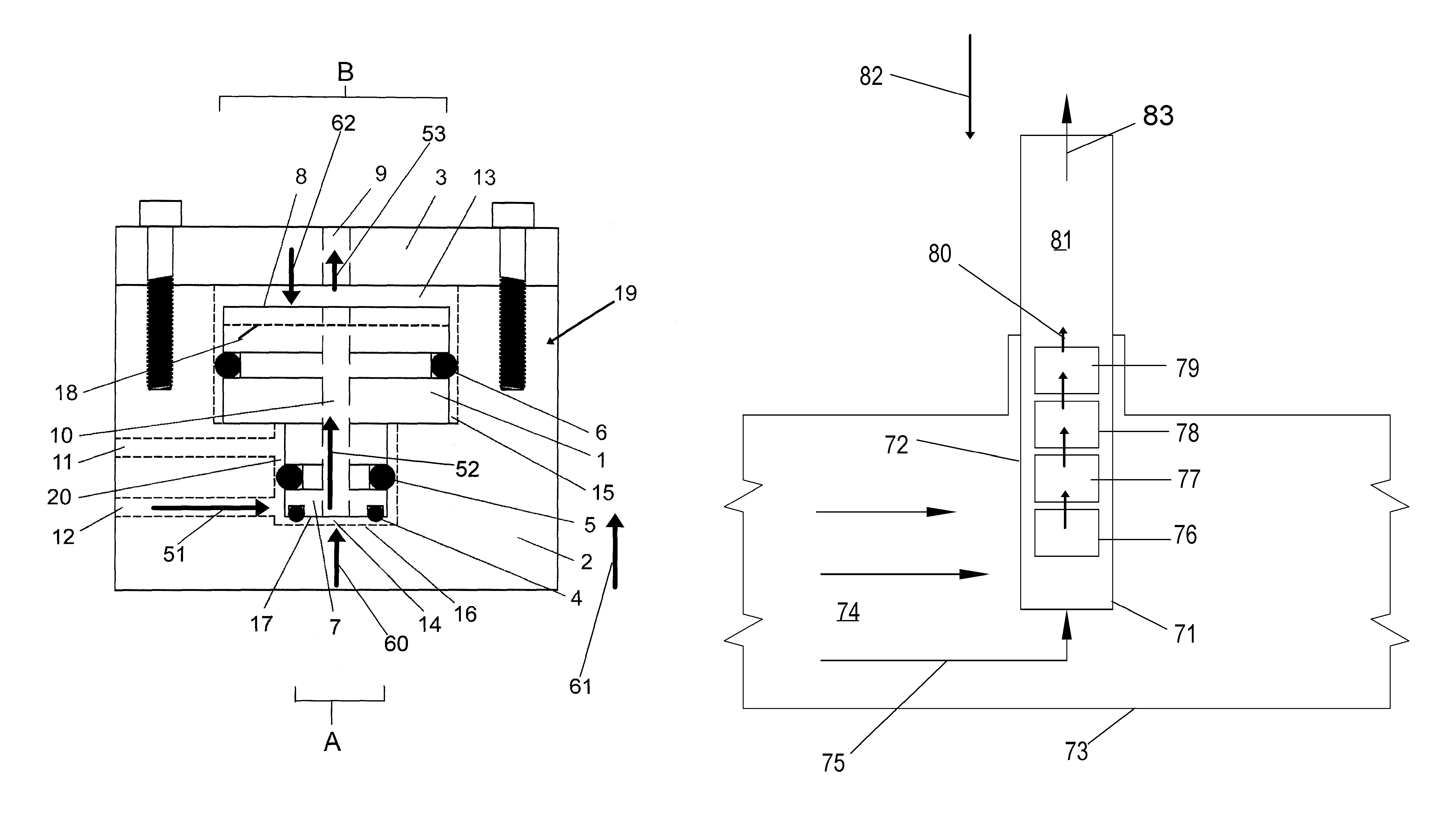
The present invention provides a system for regulating the pressure of a natural gas sample gas stream during pressure reduction and regulation in a way that prevents the negative J-T cooling effect. By using a ratio for each stage of pressure reduction, the system ensures a balanced and uniform distribution of J-T effect cooling among the stages. The gas is then reheated to prevent temperature drops and sample distortion. In addition, the system can be integrated into a sample probe pressure regulator, allowing for multiple stages inside a pipeline. The invention also provides a technique to regulate and maintain a constant and stable secondary pressure, and it can be done using a system internal to the source gas supply containment vessel or pipeline.

Problems solved by technology

Additionally, some onshore produced gas, particularly in low ambient temperature regions, is susceptible to condensation of low volatility components.
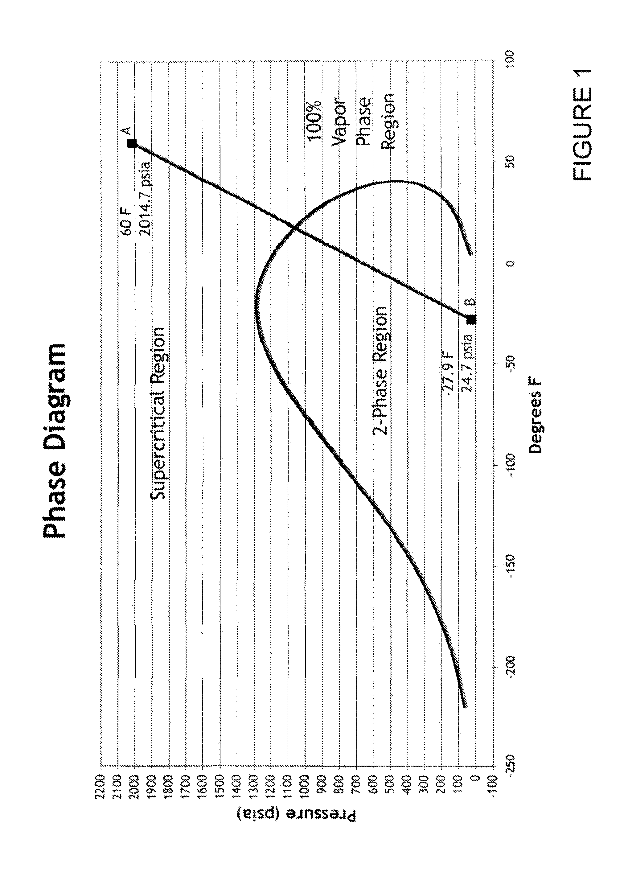
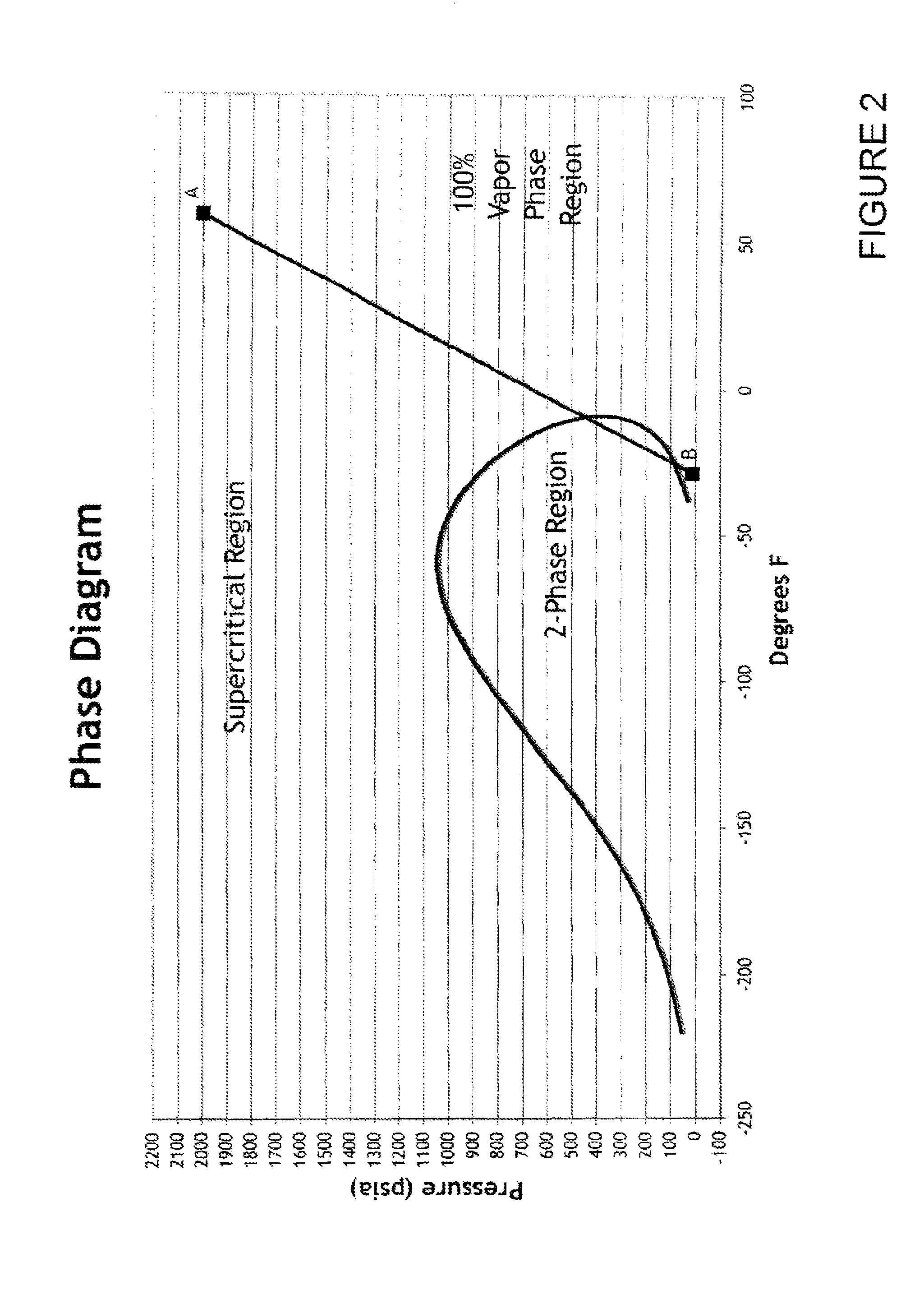
The sample gas at point B no longer conforms to the Industry standards and is no longer representative of the original source gas.
When this occurs, the possibility exists for the transitional liquid formed to become separated from the gas phase, thereby causing compositional differences along a sample gas passageway.
However it is not always safe or practical to preheat the gas sample to the required level.
An additional problem which occurs during pressure reduction and regulation of a high pressure gas, is the instability of the secondary pressure or “set pressure”.
In many analytical applications, changes in the sample gas pressure feeding an analyzer has a negative impact on its accuracy.
However, as previously mentioned, there are cases wherein, at the initial and reduced pressure, the gas is totally in the gas phase but has traversed through the 2-Phase region, thereby subjecting it to distortion from condensation.
As previously mentioned, there are cases where a single stage of pressure reduction, providing essentially an adiabatic pressure drop, can result in distortion of the sample gas composition by cooling the gas below its hydrocarbon dew-point.
Prior art, multi-stage pressure regulators are bulky and typically limited to two stages.
Therefore, prior art multi-stage pressure regulators designs do not address the major issues involved in the modern day sampling of Natural gas for compositional analysis.
Additionally, the actual J-T cooling effect distribution between the two stages varies significantly, and by reducing the gas pressure from 2014.7 to 514.7 in one stage at essentially adiabatic condition utilizing conventional methods, the gas is cooled sufficiently to penetrate the 2-Phase region, resulting in distortion of the a gas sample composition derived therefrom.
Accordingly, it is believed that the prior art has failed to provide a system to reduce and regulate a hydrocarbon sample gas stream pressure in a manner so as to prevent condensation from occurring during and after its transition from high to low pressure due to J-T cooling.
In addition, it is further believed that the prior art has failed to provide a method to regulate and maintain a constant and stable secondary pressure independent of variations of the primary (upstream supply pressure).

Method used


Image

  • Multi-stage ratio pressure regulator system
  • Multi-stage ratio pressure regulator system
  • Multi-stage ratio pressure regulator system

Examples


example

Given

[0061]PLa=114.7 PSIA[0062]RP=14.7 PSIA[0063]SAa=1 square inch[0064]SAb=2 square inches[0065]PCR=1 tO 2 or ½ or 0.5

[0066] PLb=⁢[(PLa-RP)⁢PCR]+RP=⁢[(114.7-14.7)⁢0.5]+14.7=⁢[(100)⁢0.5]+14.7=⁢50+14.7=⁢64.7

[0067]Force “A” (Fa) is the result of applying the differential pressure across fluid seal 5 to SAa. In a similar manner Force “B” (Fe) results from applying the differential pressure across fluid seal 6 to SAb.

[0068]Said differential pressures calculations require subtraction of the RP from PLa and PLb. The net result is that the incoming fluid to a single stage pressure ratio regulator, at PLa, is reduced by a specific ratio after first subtracting the RP. This is a very useful characteristic which allows pressure ratio control of a fluid only in a pressure range above the RP. Therefore, PLb can be made to remain above a given RP providing that PLa does not dip below said given PR.

[0069]For example, if in a given application a minimum of 500 PSIA is required exit of passage 9 (P...


PUM


Abstract

A multi-stage pressure regulator system. The system of the present invention provides for distribution of the Joules-Thomson (J-T) cooling effect between multiple stages. In the preferred embodiment of the present invention, the pressure is first reduced by a set ratio in one or more stages followed by an adjustable pressure output stage. The present invention thereby provides a system to control pressure reduction and thus prevent condensation (and associated distortion of a vapor composition sample) of a gas due to J-T cooling effect. The system of the present invention is particularly suitable for use placement (via, for example, a probe) within the source gas supply containment vessel, pipeline or the like, so that pressure reduction occurs at or near isothermal conditions, further lessening the likelihood of J-T condensation.

Description

PRIORITY CLAIM[0001]The present application is a continuation in part of U.S. Utility patent application Ser. No. 12 / 131,987, entitled “Multi-Stage Ratio Pressure Regulator System”, filing date Jun. 3, 2008, now U.S. Pat. No. 8,220,479 listing Donald P Mayeaux as inventor.TECHNICAL FIELD OF INVENTION[0002]The present invention relates to a multi-stage pressure regulator in which pressure is first reduced by a set ratio in one or more stages, so as to provide for distribution of the Joules-Thomson (J-T) cooling effect between multiple stages. This is useful in an analytical application, where the J-T cooling effect resulting from a large pressure drop would cool a gas below its dew-point temperature, resulting in condensation of some components, which would distort the vapor composition.BACKGROUND OF INVENTION[0003]The heating value of natural gas has a significant impact on its monetary value. In general, the heating value of natural gas increases as the concentration of low volatil...

Claims


Application Information

Patent Timeline
Patent Type & Authority Patents(United States)
IPC IPC(8): F17D1/00
CPCY10S137/906F17D1/00Y10T137/0379Y10T137/7795Y10T137/87917Y10T137/7808F17C2205/0338F17C2205/0382F17C2221/033F17C2227/036G05D16/103G05D16/0402
Inventor MAYEAUX, DONALD, P
Owner MAYEAUX HLDG
Learn More