
Method and apparatus for forcing a call to a carrier provided voice mail facility

a voice mail facility and telephone call technology, applied in the field of telephones, can solve the problem that the callee cannot answer the first signaling call, and achieve the effect of reducing the number of calls

Active Publication Date: 2013-12-10
MOBILESPHERE
View PDF34 Cites 35 Cited by
  • Summary
  • Abstract
  • Description
  • Claims
  • Application Information

AI Technical Summary

Benefits of technology

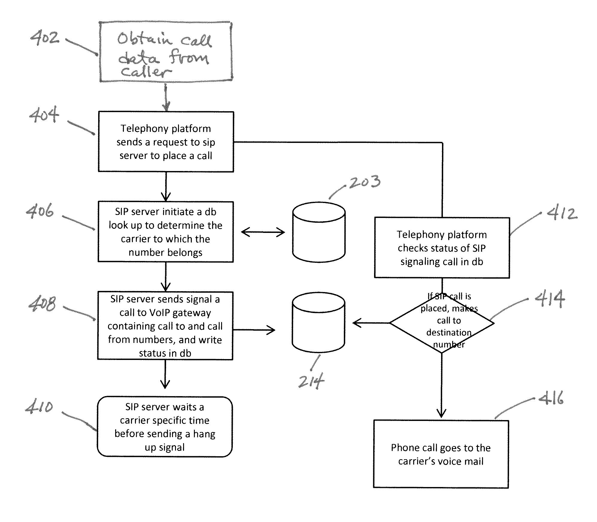
The patent describes a system and technique for making direct calls to a carrier's voicemail facility by specifying the callee's telephone number. The system initiates two calls, one to confirm the connection with the callee and another to establish the actual voice message. The first call is made without alerting the callee and is confirmed to be successful. The second call is made after a predetermined time period to avoid alerting the callee. The technique allows for quick and easy communication with the carrier's voicemail facility without needing to track down the callee's number or establish a connection through a call center.

Problems solved by technology

In this manner, the first signaling call cannot be answered by the callee, as the callee is not aware of the signaling calls presence since the duration of the call was not long enough to alert the callee.

Method used


Image

  • Method and apparatus for forcing a call to a carrier provided voice mail facility
  • Method and apparatus for forcing a call to a carrier provided voice mail facility
  • Method and apparatus for forcing a call to a carrier provided voice mail facility

Examples


Embodiment Construction

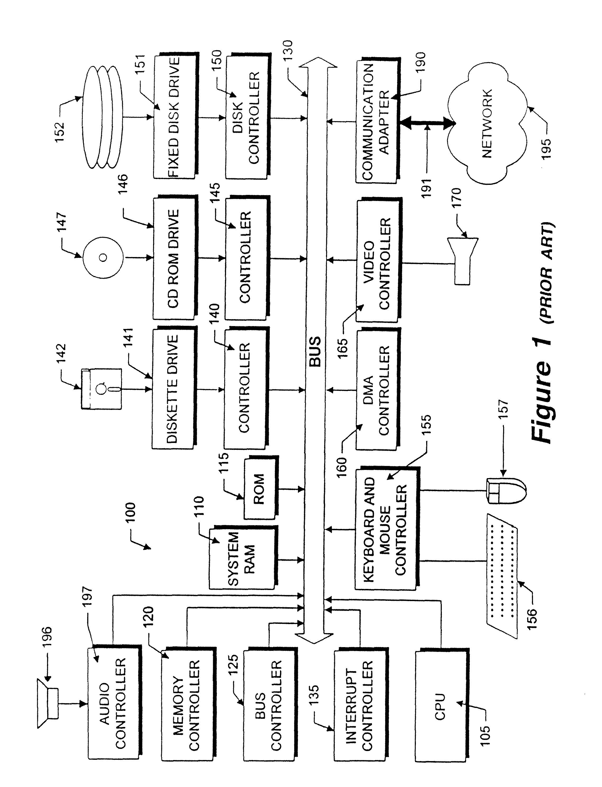
[0024]FIG. 1 illustrates the system architecture for a computer system 100 with which the various computing elements of the disclosed system may be implemented. The exemplary computer system of FIG. 1 is for descriptive purposes only. Although the description may refer to terms commonly used in describing particular computer systems, such as a Personal Computer or other microprocessor base computer architectures, the description and concepts equally apply to other systems, including systems having architectures dissimilar to FIG. 1.

[0025]Computer system 100 includes a central processing unit (CPU) 105, which may be implemented with a conventional microprocessor, a random access memory (RAM) 110 for temporary storage of information, and a read only memory (ROM) 115 for permanent storage of information. A memory controller 120 is provided for controlling RAM 110.

[0026]A bus 130 interconnects the components of computer system 100. A bus controller 125 is provided for controlling bus 13...


PUM


Abstract

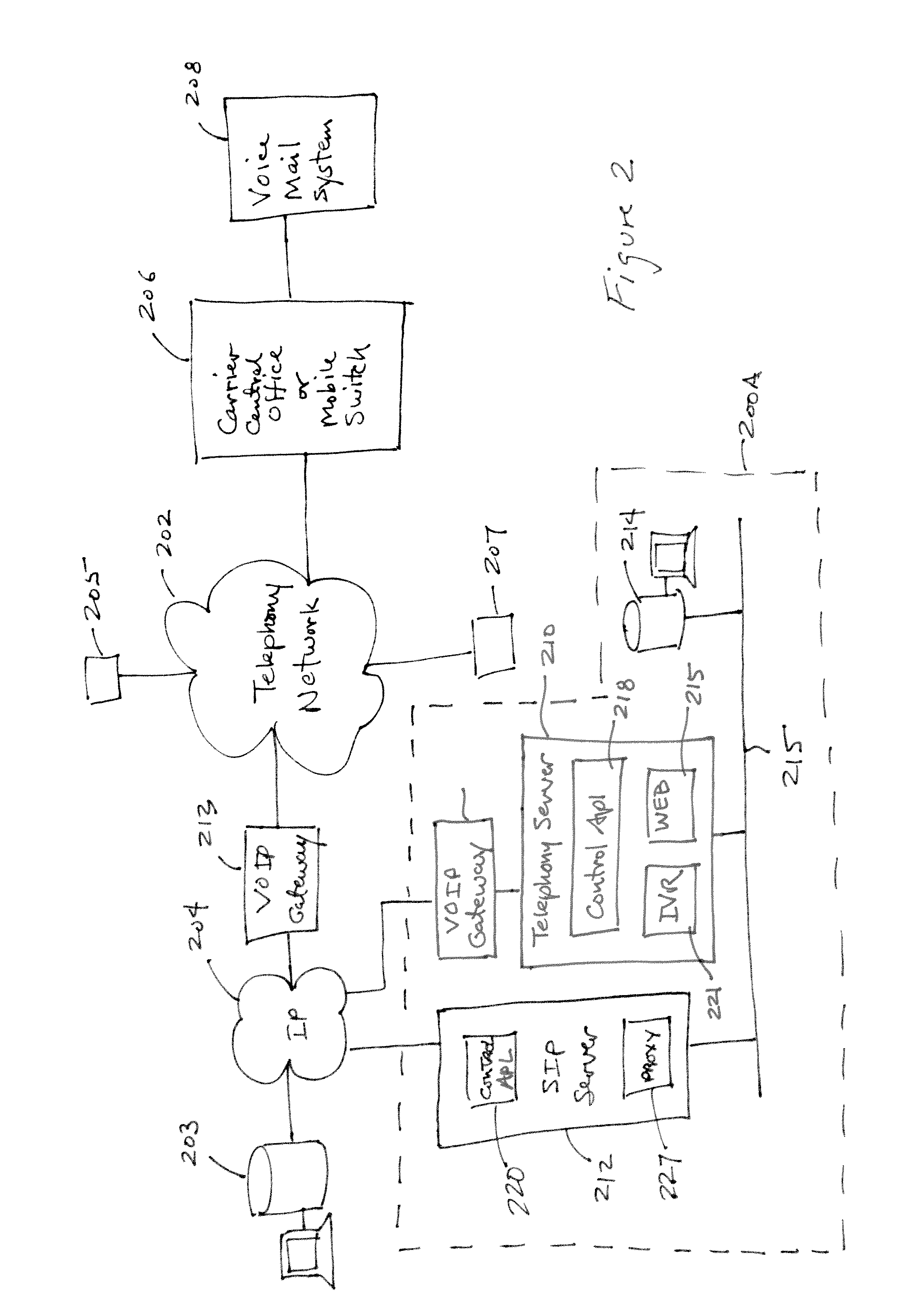
Disclosed are systems and techniques by which a caller may specify a callee's telephone number and be connected directly to a carrier provided voice mail facility associated with the identified the telephone number, even though the callee's carrier may not be the same as the caller's carrier. In the disclosed technique, a telephony server places a “Send a call” request to a server which then sends a signaling call that busies out the channel associated with the callee. The telephony server places a second call (the actual voice message) upon confirmation that the signaling call has been initiated, forcing the second call to the carrier's voice mail facility associated with the callee, since the first signaling call busied the first channel. Prior to sending the signaling call, a database look up is performed to determine which carrier services the callee number. Once the carrier is determined, another memory look up is performed to determine the time delay associated with that carrier. The time delay is then counted upon initiation of the first signaling call and the signaling call terminated upon expiration of the delay period. A user interface is provided by which a caller may specify the number of the intended callee by either a web interface, an external telephony interface such as an Interactive Voice Response (IVR) facility, an interface mechanism internal to a caller's private telephony network, or an automated number capture mechanism.

Description

FIELD OF THE INVENTION[0001]This disclosure relates generally to the field of telephony, more specifically, to a method and system for forcing a telephone call to a carrier provided voice mail facility associated with the callee.BACKGROUND OF THE INVENTION[0002]The advent of voice machines connectable to traditional telephony equipment, and, more recently, voicemail services offered by a telephone carrier, have created the ability for asynchronous voice. The ability to communicate asynchronously using voice data provides a viable option to real-time or synchronous, particularly when a callee is difficult to reach. In addition, it is not always desirable to establish voice communication directly with the callee. For example, a caller may desire to leave a voice message with a particular callee, however, establishing a call at that particular instance may not be appropriate because of different time zones, business etiquette, or other reasons to avoid a direct real-time communication ...

Claims


Application Information

Patent Timeline
Patent Type & Authority Patents(United States)
IPC IPC(8): H04M11/00H04L12/16G06F12/00
CPCH04L12/16H04M11/00H04M3/42289H04M3/53316H04M3/53325H04M3/53366
Inventor MOBARAK, TOUFIC BOUTROSHAN, ASHOU
Owner MOBILESPHERE
Learn More