Resistance simulation and common mode rejection for digital source-measure units

a technology of resistive simulation and common mode rejection, applied in the direction of electric variable regulation, process and machine control, instruments, etc., can solve the problems of increasing the achieve the effect of reducing the accuracy requirement on the dac, noise rejection advantages, and adding flexibility of the smu

Active Publication Date: 2013-12-10
NATIONAL INSTRUMENTS
View PDF13 Cites 6 Cited by
  • Summary
  • Abstract
  • Description
  • Claims
  • Application Information

AI Technical Summary

Benefits of technology

[0019]The readback values (for the measured current and / or voltage) may be obtained by averaging the current and / or voltage values received from the ADCs. The averaging may be weighted to provide noise rejection advantages. Placing the control loop in the digital domain may result in added flexibility of the SMU, and a decrease in the accuracy requirements on the DAC. The digital control loop may also offer the possibility of novel approaches for solving potential range-switching issues that may arise within the SMUs.
[0021]Overall, embodiments of an SMU comprising a digital loop controller may offer a number of advantages. For example, DAC errors may be corrected by the digital loop, reducing the accuracy requirements on the DAC. The control algorithm may be as simple or as complex as desired, and may be configured ranging from a simple integrator to a nonlinear adaptive system, thereby offering the potential to enhance stability and speed. It may also be possible to generate functions beyond the standard current-limited voltage source and voltage-limited current source. For example, it may be possible to generate constant power or constant resistance functions. In addition, voltage range switching may be performed transparently, and current range switching, potentially requiring shunt switching, may be performed more accurately.
[0022]In one set of embodiments, digital SMUs may be designed with a digital implementation of simulated resistance having high resolution, accuracy, and range. Some embodiments may simulate resistor values within a full −10Ω to 10Ω range for output currents in the 100 mA range, with a sub-200μΩ resolution (i.e. a resolution of under 200μΩ). The range may be expanded (possibly accompanied by a reduction in resolution) up to 100 kΩ for output currents in the 10 μA range. This may be applicable for Thévenin implementations, as well as Norton implementations. Furthermore, by combining the Norton and Thévenin implementations, a “pure resistance” mode may be created and used to simulate any desired resistance value. Finally, a variation of the general resistance-simulation technique may be deployed to compensate for Common Mode Voltage effects in the current measurement path, providing tighter output and measurement specifications at a lower component cost.

Problems solved by technology

Placing the control loop in the digital domain may result in added flexibility of the SMU, and a decrease in the accuracy requirements on the DAC.

Method used


Image

  • Resistance simulation and common mode rejection for digital source-measure units
  • Resistance simulation and common mode rejection for digital source-measure units
  • Resistance simulation and common mode rejection for digital source-measure units

Examples


Embodiment Construction

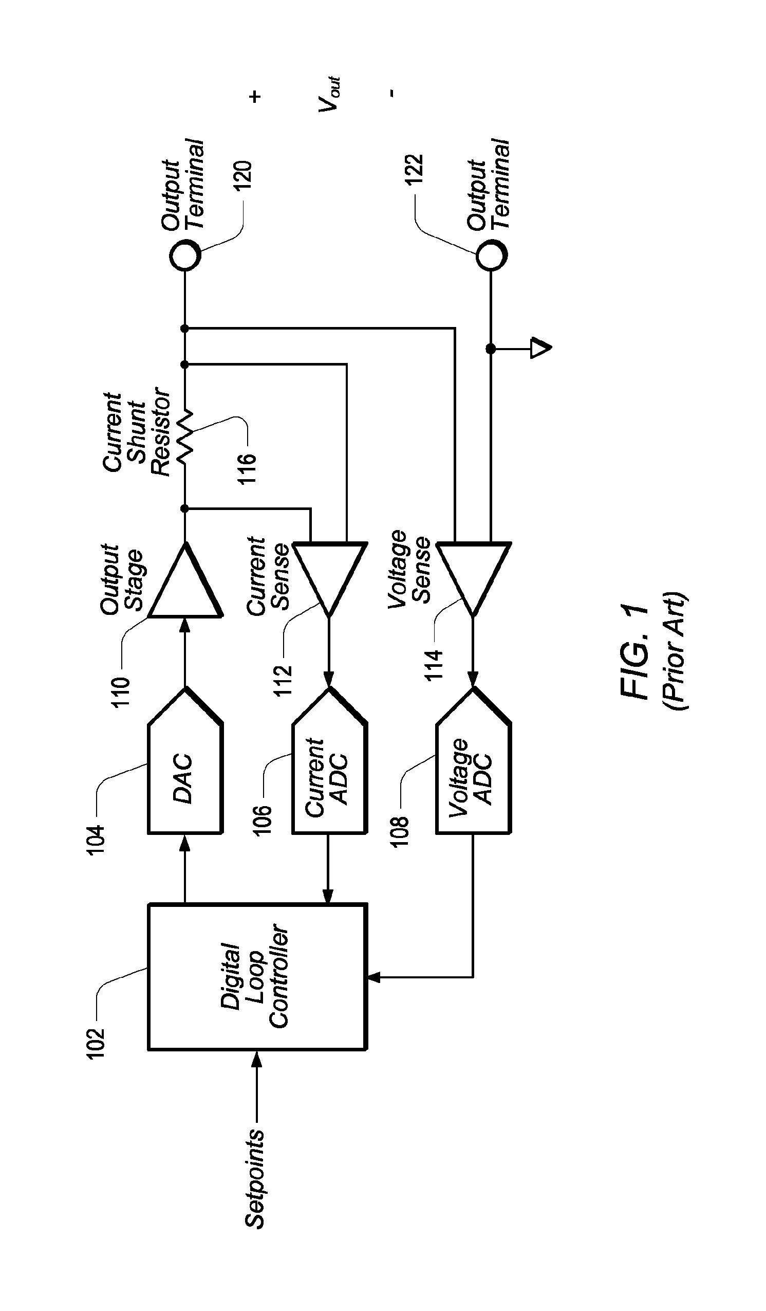
[0035]FIG. 1 shows the basic architecture of one embodiment of a prior art SMU (source-measure unit) in which the entire control loop has been configured in the digital domain. A DUT (device under test), not shown, may be coupled between output terminals 120 and 122. Setpoints and compliance limits may be provided (programmed) to Digital Loop Controller (DCL) 102, which may provide a control output through DAC (digital-to-analog converter) 104 to Output Stage 110. Feedback from Output Stage 110 may be provided to Current ADC (analog-to-digital converter) 106 and Voltage ADC 108 via respective Current Sense element 112 and Voltage Sense element 114. The current feedback may be taken from the current flowing through current shunt resistor 116, and the feedback voltage may be taken from across output terminals 120 and 122. Current ADC 106 and Voltage ADC 108 may then provide the readback current and voltage values into DCL 102.

[0036]DCL 102 may be configured to check the measured curre...


PUM


Abstract

A source-measure unit (SMU) may be implemented with digital control loops. The output voltage and output current may be measured with dedicated ADCs (analog-to-digital converters), and the readings obtained by the ADCs may be compared to a setpoint in a digital loop controller, which may produce an output to drive a DAC (digital-to-analog converter) to maintain the output voltage and / or output current at a desired setpoint. The digital loop controller may also digitally implement simulated resistance with high resolution, accuracy, and range, using Thévenin and Norton power supply models. Simulated resistor values may range from 10Ω to 10Ω for output currents in the 100 mA range, with a sub-200μΩ resolution. The range may be expanded up to 100 kΩ for output currents in the 10 μA range. The Norton and Thévenin implementations may be combined, and a “pure resistance” mode may be created for simulating any desired resistance value. A variation of the general resistance-simulation technique may also be used to compensate for Common Mode Voltage effects in the current measurement path, providing tighter output and measurement specifications at a lower component cost.

Description

BACKGROUND OF THE INVENTION[0001]1. Field of the Invention[0002]This invention relates generally to measurement and data acquisition systems and, more particularly, to the design of digital source-measure units.[0003]2. Description of the Related Art[0004]Scientists and engineers often use measurement systems to perform a variety of functions, including measurement of a physical phenomena, a unit under test (UUT), or device under test (DUT), test and analysis of physical phenomena, process monitoring and control, control of mechanical or electrical machinery, data logging, laboratory research, and analytical chemistry, to name a few examples.[0005]A typical measurement system comprises a computer system, which commonly features a measurement device, or measurement hardware. The measurement device may be a computer-based instrument, a data acquisition device or board, a programmable logic device (PLD), an actuator, or other type of device for acquiring or generating data. The measure...

Claims


Application Information

Patent Timeline
Patent Type & Authority Patents(United States)
IPC IPC(8): G05F1/00
CPCG05F1/10H01C10/00G01R31/2841
Inventor REGIER, CHRISTOPHER G.ORTEGA-POHLENZ, L. ROLANDO
Owner NATIONAL INSTRUMENTS
Why Eureka
Try Eureka