
Power management system for multi-carriers transmitter

a power management system and transmitter technology, applied in the direction of transmission, gain control, gated amplifiers, etc., can solve the problems of increasing the bandwidth requirement of the power management system, making the related art approach of modulating the vcc pef via the full-size switcher b>14/b> no longer practicabl

Active Publication Date: 2013-11-19
QORVO US INC
View PDF142 Cites 96 Cited by
  • Summary
  • Abstract
  • Description
  • Claims
  • Application Information

AI Technical Summary

Benefits of technology

The present patent discloses a power management system for a multi-carpromoter that uses envelope tracking or pseudo envelope following for high data rate applications. The system includes two switchers and a mode switch which can selectively couple the power output of the first switcher to the power output of the second switcher. This allows for more efficient power management for the multi-carpromoter. The system also includes an analog multiplexer and operational amplifiers to provide feedback to the control input of the switches. The technical effects include improved efficiency and dynamic power management for multi-carpromoters.

Problems solved by technology

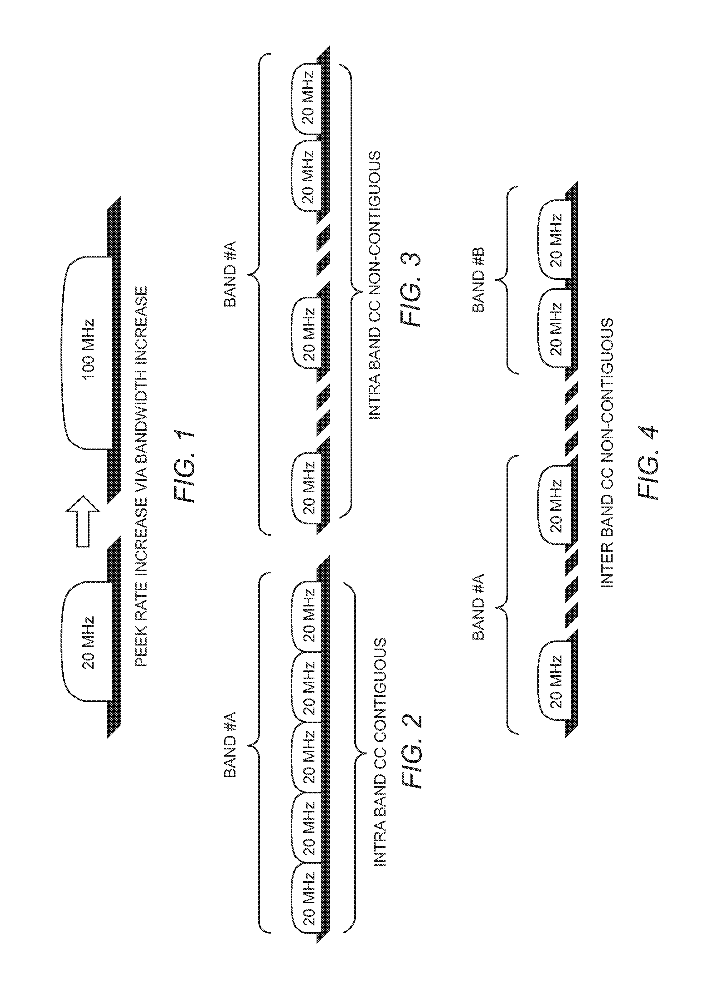
FIG. 3 is a spectrum diagram depicting intra band CC that are non-contiguous within the band A. In this case, the problem of increased bandwidth requirement for a power management system is made even worse since the spectrum is not used in a contiguous manner.
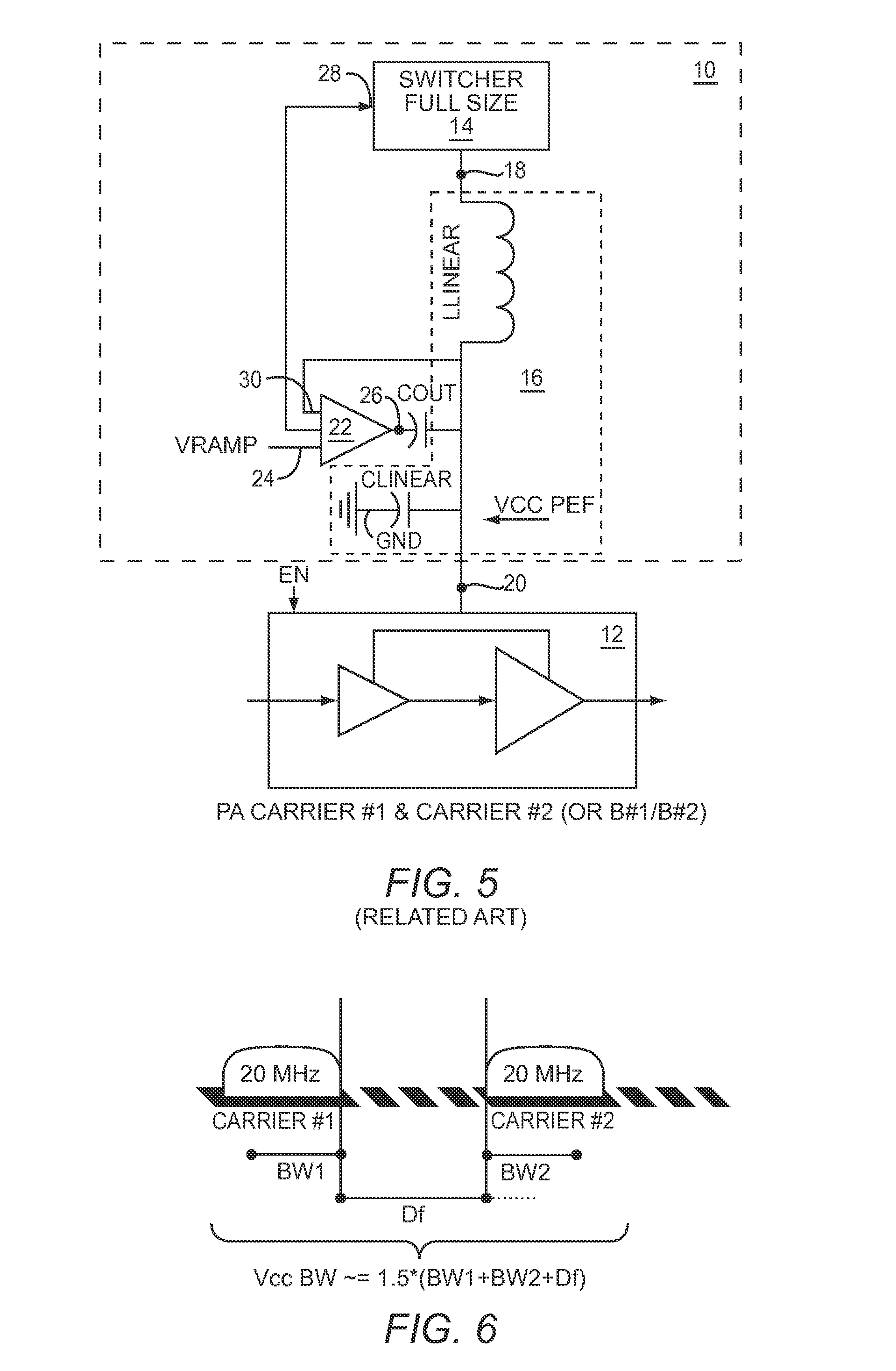
At some point, the offset frequency Df is large enough that related art approaches for modulating the VCC PEF via the full size switcher 14 are no longer practical.

Method used


Image

  • Power management system for multi-carriers transmitter
  • Power management system for multi-carriers transmitter
  • Power management system for multi-carriers transmitter

Examples


Embodiment Construction

[0030]The embodiments set forth below represent the necessary information to enable those skilled in the art to practice the disclosure and illustrate the best mode of practicing the disclosure. Upon reading the following description in light of the accompanying drawings, those skilled in the art will understand the concepts of the disclosure and will recognize applications of these concepts not particularly addressed herein. It should be understood that these concepts and applications fall within the scope of the disclosure and the accompanying claims.

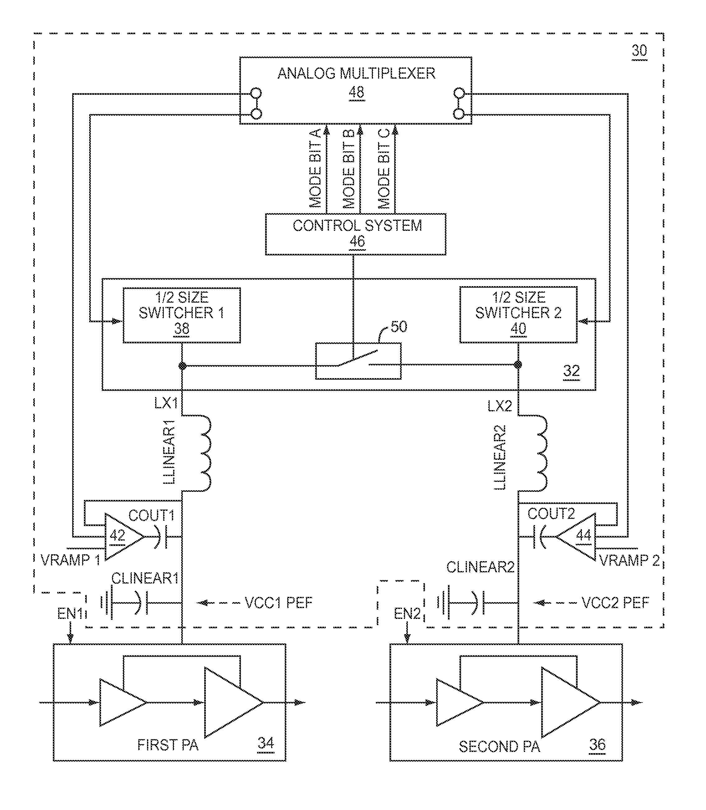
[0031]FIG. 7 depicts a multi-band power management system 30 for multi-carriers that is in accordance with the present disclosure. The multi-band power management system 30 includes a full size power converter 32 that converts power from an energy source such as a battery (not shown) to power levels that are appropriate for a first PA 34 and a second PA 36. The full size power converter 32 includes a first ½ size switcher 38 and a sec...


PUM


Abstract

A power management system for a multi-carriers transmitter is disclosed. The power management system includes a first switcher having a control input and a power output, and a second switcher having a control input and a power output. Also included is a mode switch having a mode control input, wherein the mode switch is adapted to selectively couple the power output of the first switcher to the power output of the second switcher in response to a mode control signal received by the mode control input. Further included is a control system adapted to generate the mode control signal. The control system is coupled to the mode control input of the mode switch.

Description

RELATED APPLICATIONS[0001]This application claims the benefit of U.S. provisional patent application Ser. No. 61 / 431,264, filed Jan. 10, 2011, the disclosure of which is incorporated herein by reference in its entirety.FIELD OF THE DISCLOSURE[0002]The present disclosure relates to a power management system for a communications system.BACKGROUND[0003]Future cellular equipment types such as handsets, notebook computers, and tablet computers will require simultaneous transmission of signals at two different frequencies, referred to as multi-carriers. These multi-carriers require a wide bandwidth for each carrier. Each of the multi-carriers typically require up to 20 MHz of bandwidth. Long term evolution (LTE-Advanced) as currently defined allows for the possibility of multi-carrier transmission in a single band or in different bands. As a result, LTE-Advanced customers will be afforded relatively large data rates.[0004]FIG. 1 is a spectrum diagram that demonstrates a peak data rate inc...

Claims


Application Information

Patent Timeline
Patent Type & Authority Patents(United States)
IPC IPC(8): H01Q11/12H04K3/00
CPCH03G3/3047H03F1/0277H03F3/24H03F3/72
Inventor KHLAT, NADIM
Owner QORVO US INC
Learn More