
Polymeric cover for robots

a technology for robots and covers, applied in the field of robot covers, can solve the problems of requiring additional maintenance work to remove paint, dust, or other debris, and a freshly painted surface may require repainting, and achieve the effects of increasing the surface energy of the polymer, enhancing the ability to retain residue, and increasing the wettability and adhesion of the polymer

Active Publication Date: 2013-11-19
BUTTERWORTH INDS
View PDF41 Cites 8 Cited by
  • Summary
  • Abstract
  • Description
  • Claims
  • Application Information

AI Technical Summary

Benefits of technology

The present invention provides a cover for a robot's spraying device that can retain fluids, such as paint, for better adhesion and prevent the need for repainting or repair. The cover is made of a flexible polymer that has its surface area and energy increased through processing, making it easier to hold fluids. This results in a cost-effective and efficient way to protect the robot from damage caused by spraying. The cover can be easily manufactured and maintained.

Problems solved by technology

This may result in a portion of the paint, which is atomized by the spraying, being emitted into the surrounding air without physically contacting the part, i.e., overspray.
As the atomized paint moves through the air within the paint booth, it may encounter other atomized paint, dust, or other debris.
This may result in the need for additional maintenance work to remove the paint, such as stripping the paint from the robot.
Additionally, when atomized paint combines with other particles, the contact of the combined particles with a freshly painted surface may require repainting that surface.
The particles released from the fibrous material of a robot cover may encounter a freshly painted surface, potentially requiring that the surface be repainted or repaired.
Additionally, the lower material cost of the polymer allows the cover to be readily replaced without the need to rework or otherwise clean the cover, further decreasing the manufacturing costs, as well as associated maintenance costs.

Method used


Image

  • Polymeric cover for robots
  • Polymeric cover for robots

Examples


Embodiment Construction

[0018]The embodiments disclosed below are not intended to be exhaustive or limit the invention to the precise form disclosed in the following detailed description. Rather, the embodiments are chosen and described so that others skilled in the art may utilize its teachings.

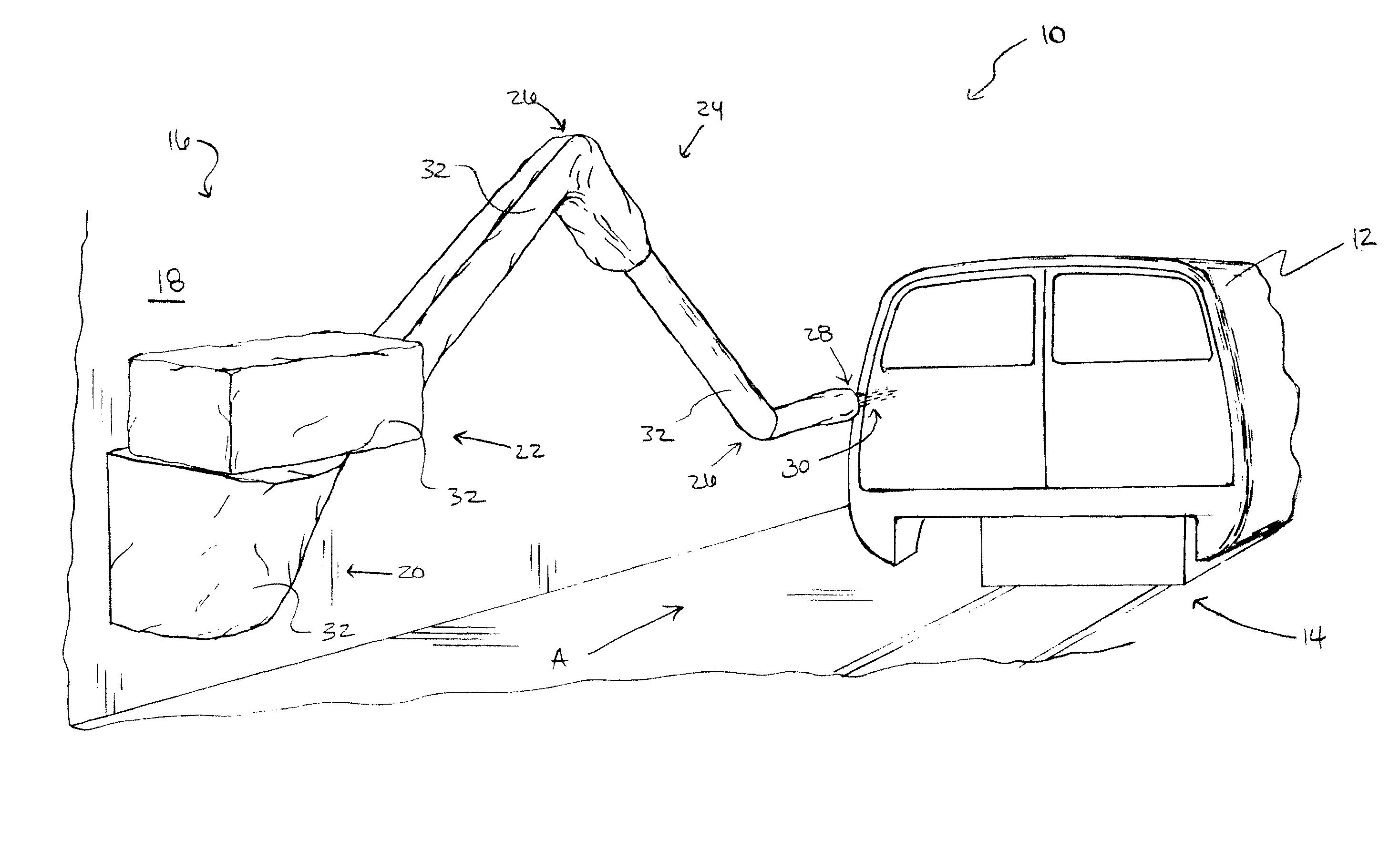
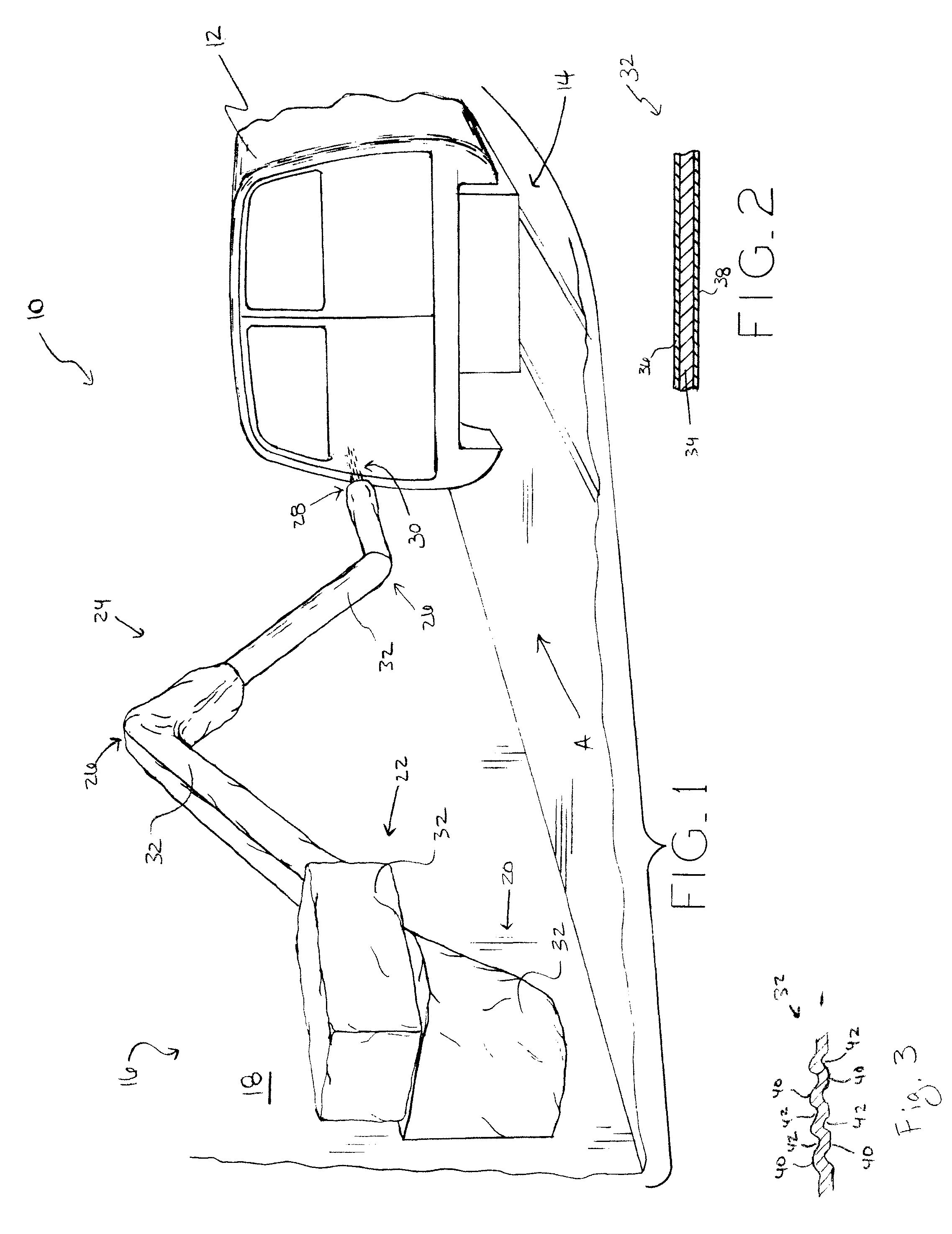
[0019]Referring to FIG. 1, paint booth 10 is shown including vehicle body 12 positioned on conveyor 14. Conveyor 14 moves vehicle body 12 along the assembly line to various assembly stations. Additionally, robot 16 is secured within paint booth 10 to wall 18. Robot 16 may be a flexible automation robot, i.e., a robot capable of articulation about a plurality of axes, or a hard automation robot, i.e., a robot that is generally stationary or capable of movement along only a single axis. Robot 16 is secured to wall 18 via base 20. Connected to base 20 of robot 16 is body 22 and arm 24. Body 22 may be actuated to rotate relative to base 20. Similarly, arm 24 may be actuated to move at pivots 26. The actuation of body 2...


PUM

PropertyMeasurementUnit
flexibleaaaaaaaaaa
surface areaaaaaaaaaaa
surface energyaaaaaaaaaa

Abstract

The present invention involves a cover for a moveable spraying device of a robot which is formed from a polymer with enhanced residue retention properties. The polymer may be processed to increase the surface energy of the polymer. For example, the polymer may be subjected to a corona treatment in order to increase its surface energy. The corona treatment process may be performed on the polymer as received, prior to cutting or otherwise manipulating the polymer. Also, the polymer may be embossed to provide the enhancement. To assemble the polymer into a robot cover, the polymer as received may be cut into individual sections for assembly. The sections may then be assembled to one another by heat sealing the sections together. The heat sealing provides a bond between the individual sections of polymer that secures the individual sections together to create the robot cover.

Description

BACKGROUND[0001]1. Field of the Invention[0002]The present invention relates to covers for robots, and, particularly, to covers for robots having spray nozzles.[0003]2. Description of the Related Art[0004]Robots are commonly used in various industrial applications to perform constant, repetitive tasks. For example, a robot may be placed on an assembly line to weld together or paint parts moving therealong. When painting a part moving along an assembly line, for example, a robot may spray the paint directly onto the moving part. This may result in a portion of the paint, which is atomized by the spraying, being emitted into the surrounding air without physically contacting the part, i.e., overspray. To help contain this atomized paint, a booth may be erected around the painting operation on the assembly line. The booth helps to contain the atomized paint and prevent the same from contacting other machinery located along or parts moving down the assembly line. As the atomized paint mo...

Claims


Application Information

Patent Timeline
Patent Type & Authority Patents(United States)
IPC IPC(8): B29C65/00
CPCB05B15/02B08B17/04B25J9/0012B25J19/0075B23P19/04Y10T29/49826Y10T428/169Y10T428/19Y10T428/1334B05B15/50
Inventor BUTTERWORTH, III, FRANK L.
Owner BUTTERWORTH INDS
Learn More