
Distributed inverter and intelligent gateway

a technology of intelligent gateway and inverter, which is applied in the direction of dc-ac conversion without reversal, power distribution line transmission, transportation and packaging, etc., can solve the problems of reducing the ac power harvesting from the entire array, commercial buildings and larger installations, and exposing the rooftops of many places not sufficiently large, so as to achieve simple and safe, improve the system, and improve the effect of reliability

Active Publication Date: 2013-11-12
ENPHASE ENERGY
View PDF48 Cites 162 Cited by
  • Summary
  • Abstract
  • Description
  • Claims
  • Application Information

AI Technical Summary

Benefits of technology

The invention is a system for installation, operation, and maintenance of a power conversion system that is simple and safe. It provides a high degree of reliability and a long lifetime to the microinverter. Additionally, the system is upgradeable during the lifetime of the system.

Problems solved by technology

Residential rooftops present a special challenge for the placement and interconnection of photovoltaic modules, due to the presence of gables, multiple roof angles, and other such obstructions.
Such rooftops often do not expose a sufficiently large, commonly directed surface to the sun for photovoltaic modules to be positioned to harvest maximum power.
This degrades the AC power harvest from the entire array.
Commercial buildings and larger installations present slightly different challenges.
In commercial buildings, large, commonly directed surfaces are generally available, but even then, obstructions, such as HVAC components must be dealt with as the components may block solar radiation.
Additionally, since such installations often consist of thousands of PV modules, monitoring, operation and maintenance can be time consuming and expensive.
Yet, the use of microinverters continues to be negligible due to their inferior reliability and efficiency as well as their high cost as compared to conventional inverters.
When microinverters are placed in proximity to PV modules, the hostile outdoor environment exacerbates the design challenge for achieving high reliability, high efficiency and low cost.
Similarly, servicing and replacing microinverters on a rooftop is potentially more challenging and labor intensive than servicing and replacing centralized inverters.
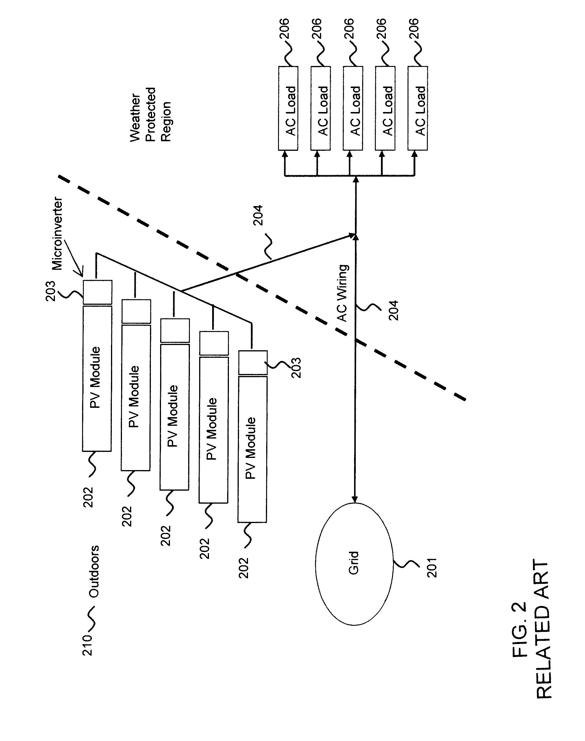
Early versions of related art for microinverters utilized electrolytic capacitors, having a lifespan susceptible to degradation at high temperatures.
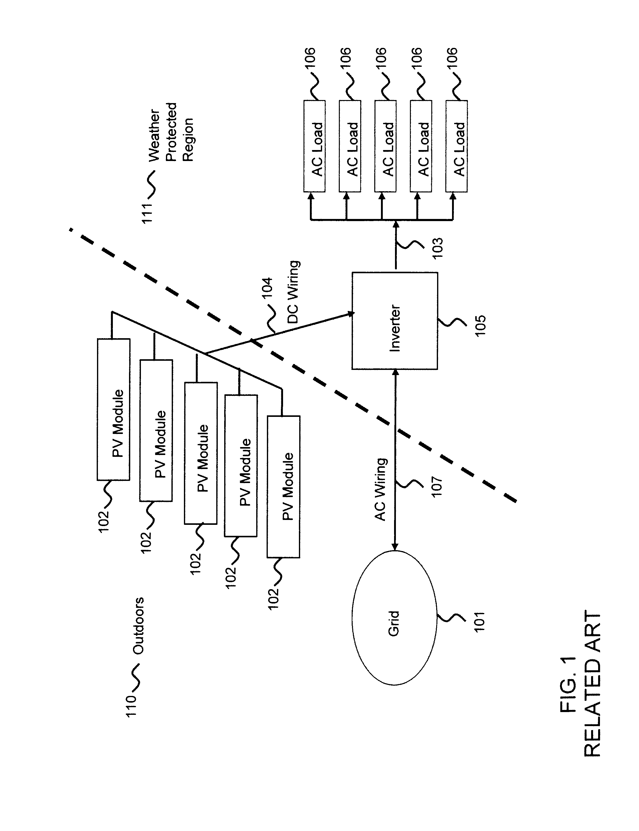
A problem with the related art microinverters is that they either collocate all inverter functions including safety and code compliance within the microinverter or they do not address how these functions are to be implemented, thereby making the design for high reliability and long life difficult and expensive.

Method used


Image

  • Distributed inverter and intelligent gateway
  • Distributed inverter and intelligent gateway
  • Distributed inverter and intelligent gateway

Examples


Embodiment Construction

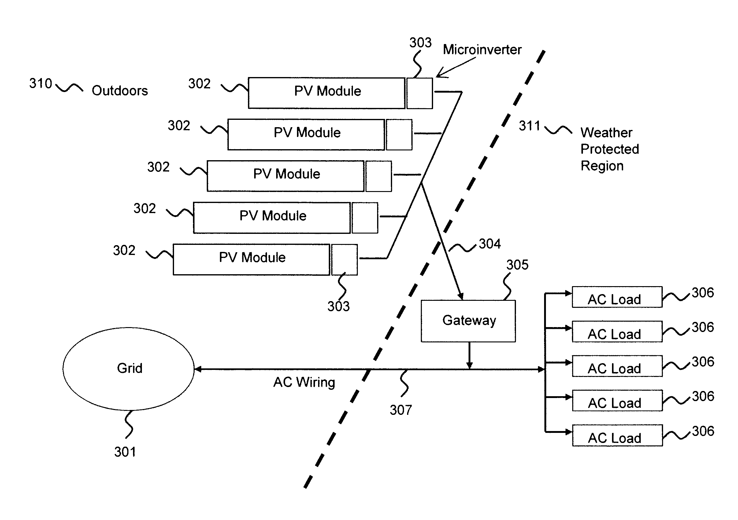
[0038]Embodiments of the invention include a novel approach whereby only those functions and components that are necessary to achieve the advantages of microinverters are placed in assemblies in proximity to the PV modules and other functions including, for example, system control, are located elsewhere. This separation of functions and components is termed partitioning. The control and coordination of the system is performed without additional wiring. Communications may occur via powerline, wired and / or wireless channels. Disabling the communications channel provides a way for turning the microinverters off thereby facilitating inverter or PV module replacement, maintenance or other desired tasks. Moreover, the partitioning provides for enhanced safety as compared to the related art. In the related art, in the presence of solar radiation, the PV module outputs are always enabled and are thus capable of electrocuting the installer. Accordingly, embodiments of the invention provide f...


PUM


Abstract

A system and apparatus for generating power. In one embodiment, the apparatus comprises a power module for coupling to a DC power source via a DC bus, wherein the power module (i) converts a first power from the DC power source to a second power, and (ii) comprises a maximum power point tracking module unit for dynamically adjusting a load voltage of the DC power source; an AC bus; and a controller, physically separate from the power module and coupled to the power module via the AC bus, for operatively controlling the power module.

Description

CROSS-REFERENCE TO RELATED APPLICATIONS[0001]This application is a continuation of co-pending U.S. patent application Ser. No. 12 / 121,616, entitled “Distributed Inverter and Intelligent Gateway” and filed May 15, 2008, which further claims the benefit of U.S. provisional patent application Ser. No. 60 / 938,663 filed May 17, 2007, both of which are herein incorporated by reference in their entirety. The present application is further related to co-pending U.S. patent application Ser. No. 12 / 121,578 entitled, “Photovoltaic AC Inverter Mount and Interconnect” and filed May 15, 2008, and U.S. patent application Ser. No. 12 / 121,580 entitled “Photovoltaic Module-Mounted AC Inverter” and filed May 15, 2008, both of which are hereby incorporated by this reference in their entirety.BACKGROUND OF THE INVENTION[0002]1. Field of the Invention[0003]The invention relates to power conversion including direct current (DC) to alternating current (AC) and, more particularly, to photovoltaic module out...

Claims


Application Information

Patent Timeline
Patent Type & Authority Patents(United States)
IPC IPC(8): H02J1/00H02J3/00
CPCH02M7/493H02J3/385H02J3/386H02J3/383Y02B10/14Y02E10/563H02J3/387Y02E10/763Y02E10/58H02J2300/30H02J2300/28H02J2300/26H02J2300/24H02J3/381Y02E10/76H02J3/40H02J3/38Y02B10/10Y02E10/56H02J3/388H02M7/44
Inventor ROTZOLL, ROBERT R.KAPUR, RAJAN N.PATIL, SUHAS S.
Owner ENPHASE ENERGY
Learn More