
Polycrystalline compacts including in-situ nucleated grains, earth-boring tools including such compacts, and methods of forming such compacts and tools

a technology of polycrystalline compacts and nucleated grains, which is applied in the field of polycrystalline compacts, can solve the problems of thermal damage in the diamond table, relatively large tensile stress at the interface between the diamond grains, and thermal degradation of the microstructur

Active Publication Date: 2013-11-12
BAKER HUGHES HLDG LLC
View PDF88 Cites 28 Cited by
  • Summary
  • Abstract
  • Description
  • Claims
  • Application Information

AI Technical Summary

Problems solved by technology

The presence of the catalyst material in the diamond table may contribute to thermal damage in the diamond table when the cutting element is heated during use, due to friction at the contact point between the cutting element and the formation.
This difference in thermal expansion may result in relatively large tensile stresses at the interface between the diamond grains, and contributes to thermal degradation of the microstructure when polycrystalline diamond compact cutting elements are used in service.
This differential in thermal expansion may result in relatively large compressive and / or tensile stresses at the interface between the diamond table and the substrate that eventually lead to the deterioration of the diamond table, cause the diamond table to delaminate from the substrate, or result in the general ineffectiveness of the cutting element.
For example, the diamond crystals may graphitize at the diamond crystal boundaries, which may substantially weaken the diamond table.
It has also been reported, however, that such fully leached diamond tables are relatively more brittle and vulnerable to shear, compressive, and tensile stresses than are non-leached diamond tables.
In addition, it is difficult to secure a completely leached diamond table to a supporting substrate.

Method used


Image

  • Polycrystalline compacts including in-situ nucleated grains, earth-boring tools including such compacts, and methods of forming such compacts and tools
  • Polycrystalline compacts including in-situ nucleated grains, earth-boring tools including such compacts, and methods of forming such compacts and tools
  • Polycrystalline compacts including in-situ nucleated grains, earth-boring tools including such compacts, and methods of forming such compacts and tools

Examples


Embodiment Construction

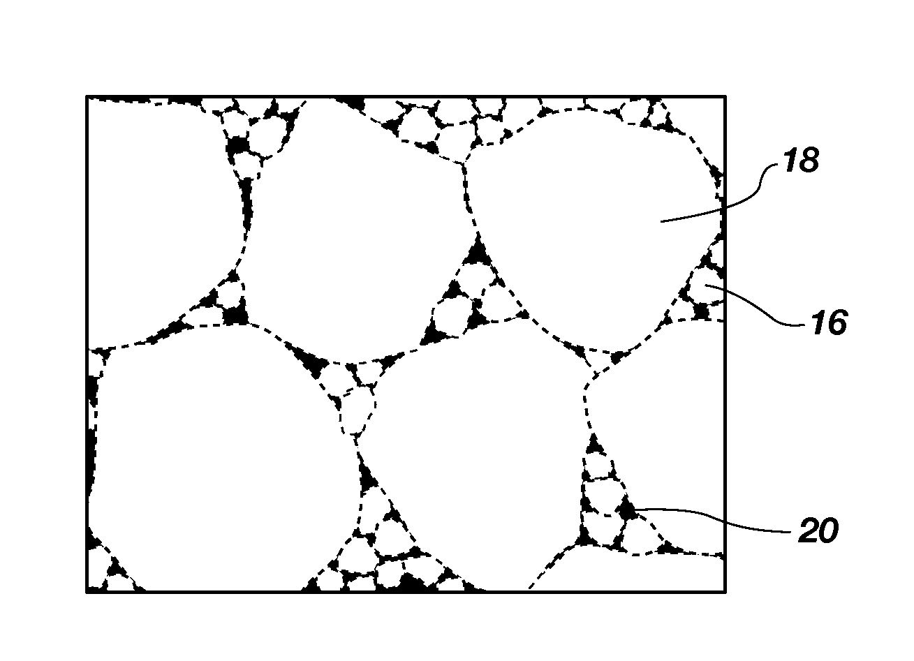
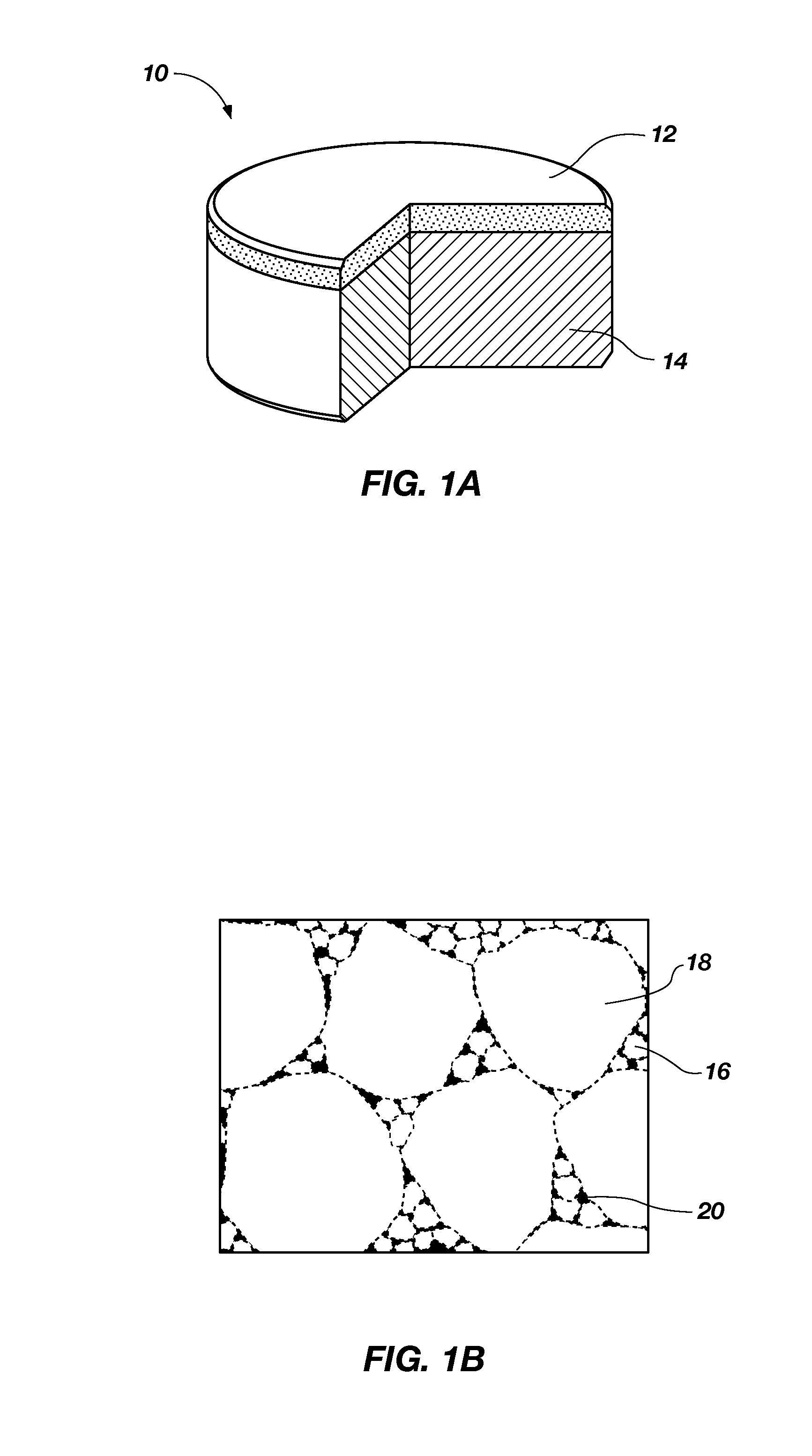
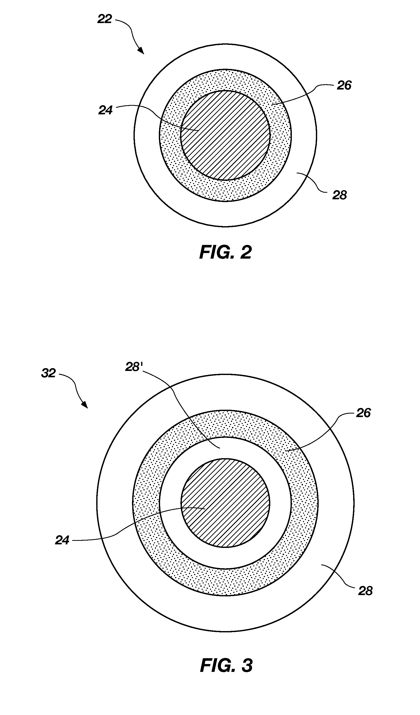
[0020]The illustrations presented herein are not actual views of any particular polycrystalline compact, microstructure of polycrystalline material, particles, or drill bit, and are not drawn to scale, but are merely idealized representations that are employed to describe embodiments of the invention. Additionally, elements common between figures may retain the same numerical designation.

[0021]As used herein, the term “drill bit” means and includes any type of bit or tool used for drilling during the formation or enlargement of a wellbore and includes, for example, rotary drill bits, percussion bits, core bits, eccentric bits, bicenter bits, reamers, expandable reamers, mills, drag bits, roller cone bits, hybrid bits and other drilling bits and tools known in the art.

[0022]As used herein, the term “fullerene” means and includes cage-like hollow molecules comprising a plurality of carbon atoms bonded together in a polyhedral structure. Fullerenes may include, for example, between abo...


PUM

PropertyMeasurementUnit
grain sizeaaaaaaaaaa

Abstract

Polycrystalline compacts include hard polycrystalline materials comprising in situ nucleated smaller grains of hard material interspersed and inter-bonded with larger grains of hard material. The average size of the larger grains may be at least about 250 times greater than the average size of the in situ nucleated smaller grains. Methods of forming polycrystalline compacts include nucleating and catalyzing the formation of smaller grains of hard material in the presence of larger grains of hard material, and catalyzing the formation of inter-granular bonds between the grains of hard material. For example, nucleation particles may be mixed with larger diamond grains, a carbon source, and a catalyst. The mixture may be subjected to high temperature and high pressure to form smaller diamond grains using the nucleation particles, the carbon source, and the catalyst, and to catalyze formation of diamond-to-diamond bonds between the smaller and larger diamond grains.

Description

CROSS-REFERENCE TO RELATED APPLICATION[0001]This application claims the benefit of U.S. Provisional Patent Application Ser. No. 61 / 232,265 filed Aug. 7, 2009, the disclosure of which is hereby incorporated herein by this reference in its entirety.TECHNICAL FIELD[0002]The present invention relates generally to polycrystalline compacts, to tools including such compacts, and to methods of forming such polycrystalline compacts and tools.BACKGROUND[0003]Earth-boring tools for forming wellbores in subterranean earth formations generally include a plurality of cutting elements secured to a body. For example, fixed-cutter earth-boring rotary drill bits (also referred to as “drag bits”) include a plurality of cutting elements that are fixedly attached to a bit body of the drill bit. Similarly, roller cone earth-boring rotary drill bits may include cones that are mounted on bearing pins extending from legs of a bit body such that each cone is capable of rotating about the bearing pin on which...

Claims


Application Information

Patent Timeline
Patent Type & Authority Patents(United States)
IPC IPC(8): E21B10/00E21B10/46E21B10/48
CPCB24D99/005B82Y30/00C01B31/06C01B31/065E21B10/567E21B10/48E21B10/46C09K3/1436Y10T428/25B22F3/14C22C26/00B01J2203/0655B22F2005/001C22C2026/001C22C2026/006C22C2026/007C22C2026/008B01J3/062B01J2203/061B01J2203/0615B01J2203/062B01J2203/0625B01J2203/068B01J2203/0685C01B32/25C01B32/28Y10T428/249967Y10T428/249921
Inventor DIGIOVANNI, ANTHONY A.SCOTT, DANNY E.
Owner BAKER HUGHES HLDG LLC
Learn More