
Capacitive spreading readout board

a readout board and readout electrode technology, applied in the field of avalanche particle detector readout electrode assembly, can solve the problems of inability to accurately detect the presence of avalanche particles,

Inactive Publication Date: 2013-11-05
EUROPEAN ORGANIZATION FOR NUCLEAR RESEARCH
View PDF4 Cites 1 Cited by
  • Summary
  • Abstract
  • Description
  • Claims
  • Application Information

AI Technical Summary

Benefits of technology

[0014]Since the number of detector pads in said second detector layer is larger than the number of detector pads in said first detector layer, the position of the incident particles can be determined with high accuracy even though only a relatively small number of readout pads in said first detector layer (and hence a corresponding small number of readout channels and electronics) is required. This reduces the cost and overall complexity of the readout system, and will enable readout boards of enlarged physical size and enhanced spatial resolution. Since capacitive spreading is fast, readout rates are high and detector times are short.
[0052]According to this latter embodiment, electron multiplication may take place in a plurality of holes extending through a foil with metal coatings on both sides. The generated electrons may then drift to the readout device, which is not involved in the amplification process itself Also, in this second detector design, the readout device according to the present invention allows to localize the event with enhanced spatial resolution and / or with a reduced number of readout pads.DETAILED DESCRIPTION OF A PREFERRED EMBODIMENT

Problems solved by technology

The spatial resolution of the detector device has conventionally been limited by the size of the individual readout pads.
However, a larger number of readout pads requires a correspondingly larger number of readout channels and electronics and hence increases both detector cost and complexity.
In fact, the number of readout channels that can be analyzed quickly with modern readout electronics places an important constraint on the size of the readout pads, and hence on the detector resolution.
However, since the dispersion of the charges in the resistive layer needs time, this results in an indesirable increase in detector dead times and a corresponding reduction in readout rates.
At the same time, it prevents the signal from spreading over a distance that would exceed one detector pad diameter in the subjacent detector layer, and might therefore reduce the spatial resolution of the detector device.

Method used


Image

  • Capacitive spreading readout board
  • Capacitive spreading readout board
  • Capacitive spreading readout board

Examples


Embodiment Construction

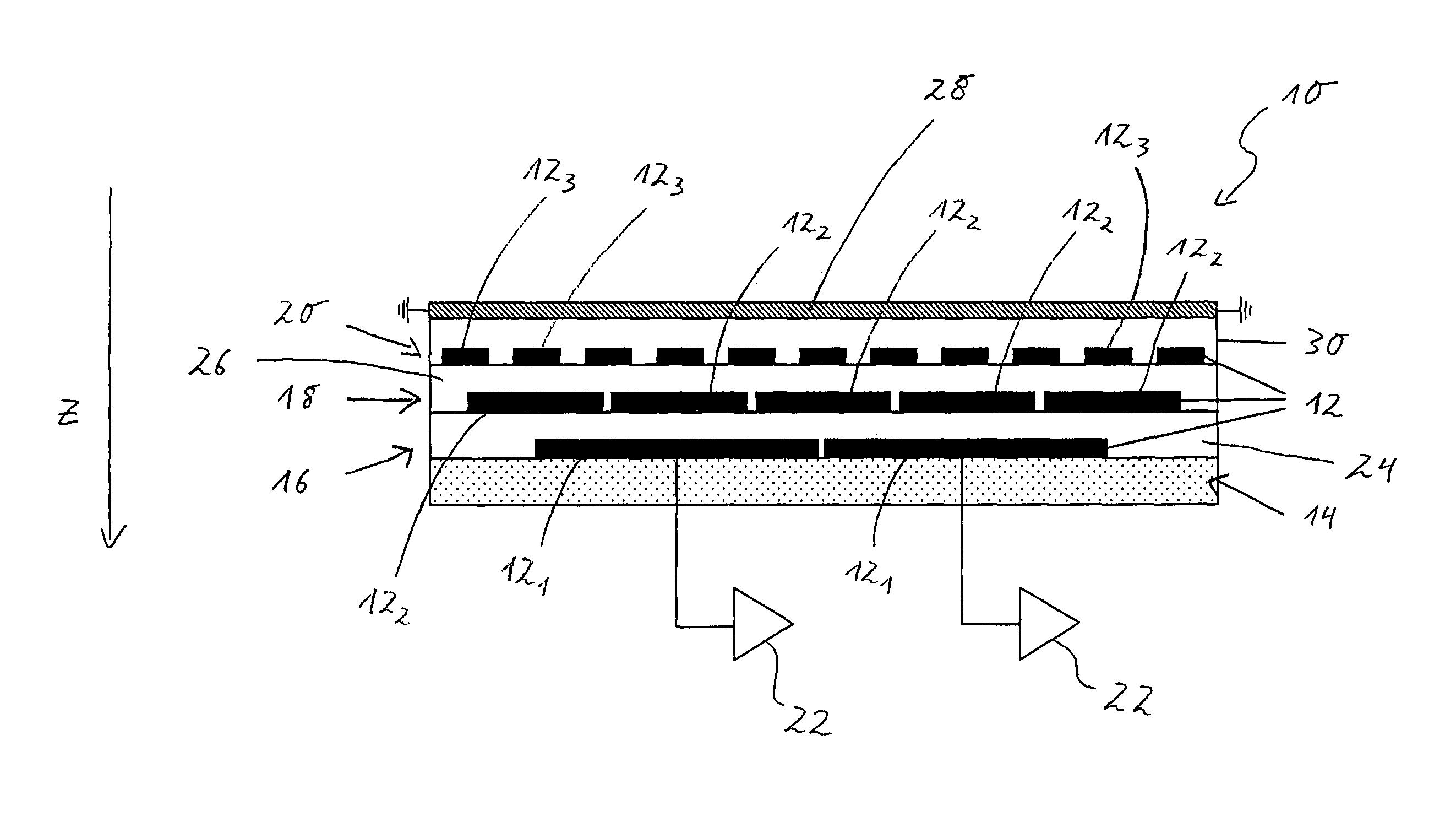
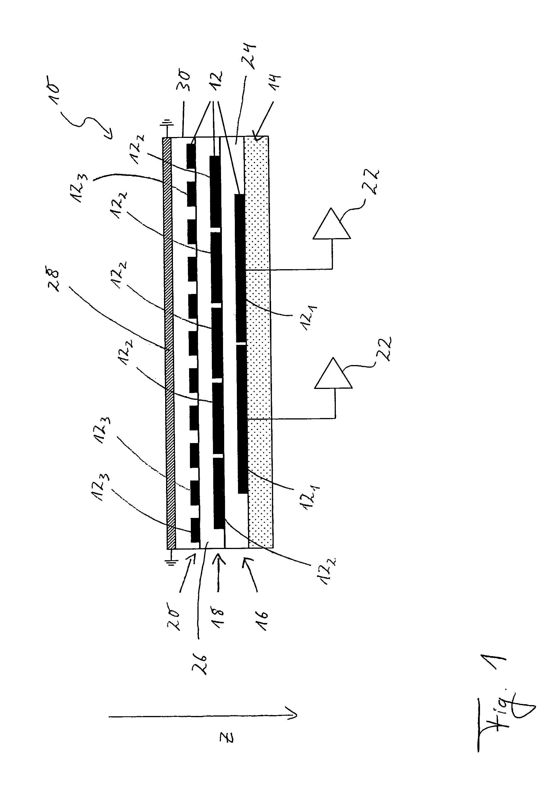
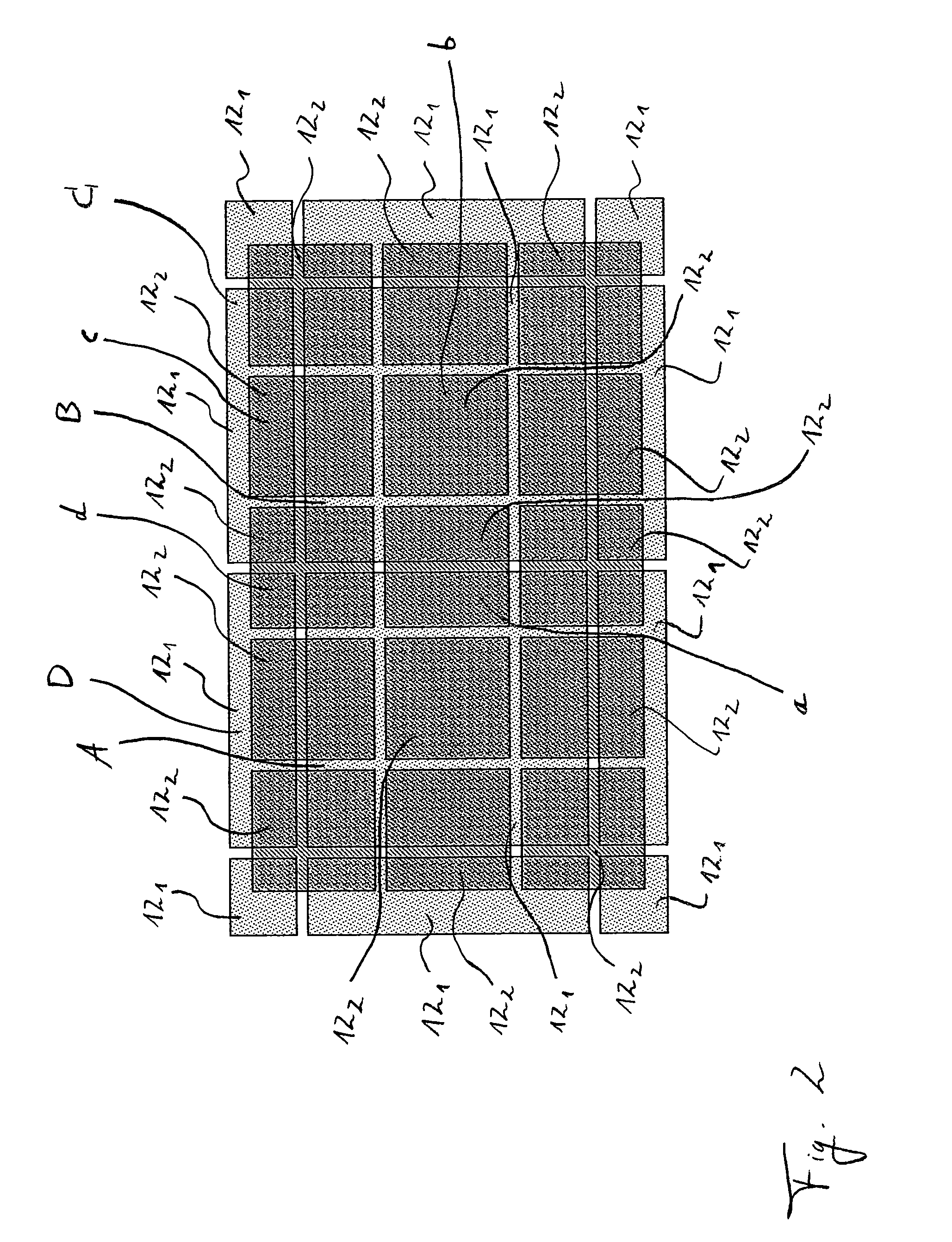
[0053]The features and numerous advantages of a capacitive spreading readout board according to the present invention can be best understood from a description of the accompanying drawings, in which:

[0054]FIG. 1 is a schematic side view of a capacitive spreading readout board according to an embodiment of the present invention;

[0055]FIG. 2 is a schematic plan view of a capacitive spreading readout board according to an embodiment of the present invention; and

[0056]FIG. 3 is a schematic side view illustrating the operation of a capacitive spreading readout board according to the present invention in a gas electron multiplier detector.

[0057]FIG. 1 is a side view of a part of a capacitive spreading readout board 10 according to the present invention. The readout board 10 shown in FIG. 1 comprises a plurality of detector pads 12 formed of copper and embedded into a common holding structure 14. The detector pads 12 are formed in said holding structure 14 to define (along a Z direction) t...


PUM


Abstract

A readout board for use in a micropattern gas detector comprises a plurality of detector pads arranged into a plurality of consecutive layers that are separated by dielectric spacer material. An electron cloud hitting the front side of the readout board will induce a charge on one of the detector pads of the uppermost layer. By capacitive coupling, the signal will propagate downwards through the consecutive layers until it reaches the bottom layer, from which the charges are read out and analyzed. The position of the impact can be determined by comparing the charges that have spread to neighboring readout pads. Since only the bottommost layer of the readout pads needs to be connected to readout electronics, incident particles can be localized at high precision despite the relatively large size of the readout pads in the bottom layer. The invention is effective both in a gas electron multiplier (GEM) and in a MicroMegas detector.

Description

FIELD OF THE INVENTION[0001]The present invention relates to a readout electrode assembly for an avalanche particle detector, in particular for a micropattern gas detector (MPGD).BACKGROUND AND STATE OF THE ART[0002]Particle detectors are devices to detect, track, and / or identify radiation or particles and find wide applications throughout particle physics, biology as well as medical technology.[0003]Particle detectors exploiting the process of ionization and charge multiplication in gases have been in use with continued improvements ever since Rutherford first employed a gas-filled wire counter to study natural radioactivity more than a century ago. Techniques for designing detectors of increased physical size and / or enhanced spatial resolution and sensitivity continue to be an active field of research in the detector community today.[0004]Gaseous detectors typically collect the electrons released by ionizing radiation and guide them to a region with a strong electric field, thereb...

Claims


Application Information

Patent Timeline
Patent Type & Authority Patents(United States)
IPC IPC(8): H01J47/00
CPCG01T1/2935G01T1/185
Inventor DE OLIVEIRA, RUI
Owner EUROPEAN ORGANIZATION FOR NUCLEAR RESEARCH
Learn More