
Linear drive and pump system, in particular an artificial heart

a pump system and linear drive technology, applied in the direction of prosthesis, magnetic circuit rotating parts, magnetic circuit shape/form/construction, etc., can solve the problems of damage to the blood, limited functionality of the heart, and insufficient number of donor hearts no longer availabl

Active Publication Date: 2013-11-05
RWTH AACHEN UNIVERSITY +1
View PDF8 Cites 1 Cited by
  • Summary
  • Abstract
  • Description
  • Claims
  • Application Information

AI Technical Summary

Benefits of technology

The patent text describes a medical device that can be implanted in patients to treat certain conditions. The device is smaller in size, which means more patients can be treated with it. Additionally, the device's service life is longer compared to previous systems. The device has a coil assembly that can be attached to a force-transmission element in the permanent-magnet assembly, which saves space and makes the device more efficient. The coil windings can be placed on a support element that is shaped like a pot, where the force-transmission element is located.

Problems solved by technology

When using systems that assist the heart, the heart is limited in its functionality, but can however continue to still fulfill a part of its original pumping capacity.
As, however, the demand for donor hearts continues to increase and simultaneously, the willingness to donate is falling, an adequate number of donor hearts is no longer available.
Particular attention is being paid to heat lost by the drive, which can damage the blood by coagulating it.
Thus, the bearings are lighter and more compact and have longer service lives.
As an ideal centering cannot be implemented technically, forces of attraction are created in all previous systems between stator and rotor or the primary part and secondary part that lead to premature wear of the bearings.
As an ideal centering cannot be done technically, there are always more or less pronounced radial forces between the two parts.
In addition to the actual guiding function, they load the bearings and lead to increased wear of the bearings, as a result of which the service life is reduced.
Previous concepts do not maximize the density of power.
Rather, the weight and the dimensions of the artificial heart are the main problem of the artificial heart because of the severely limited space in the chest cavity at a specified propelling thrust.
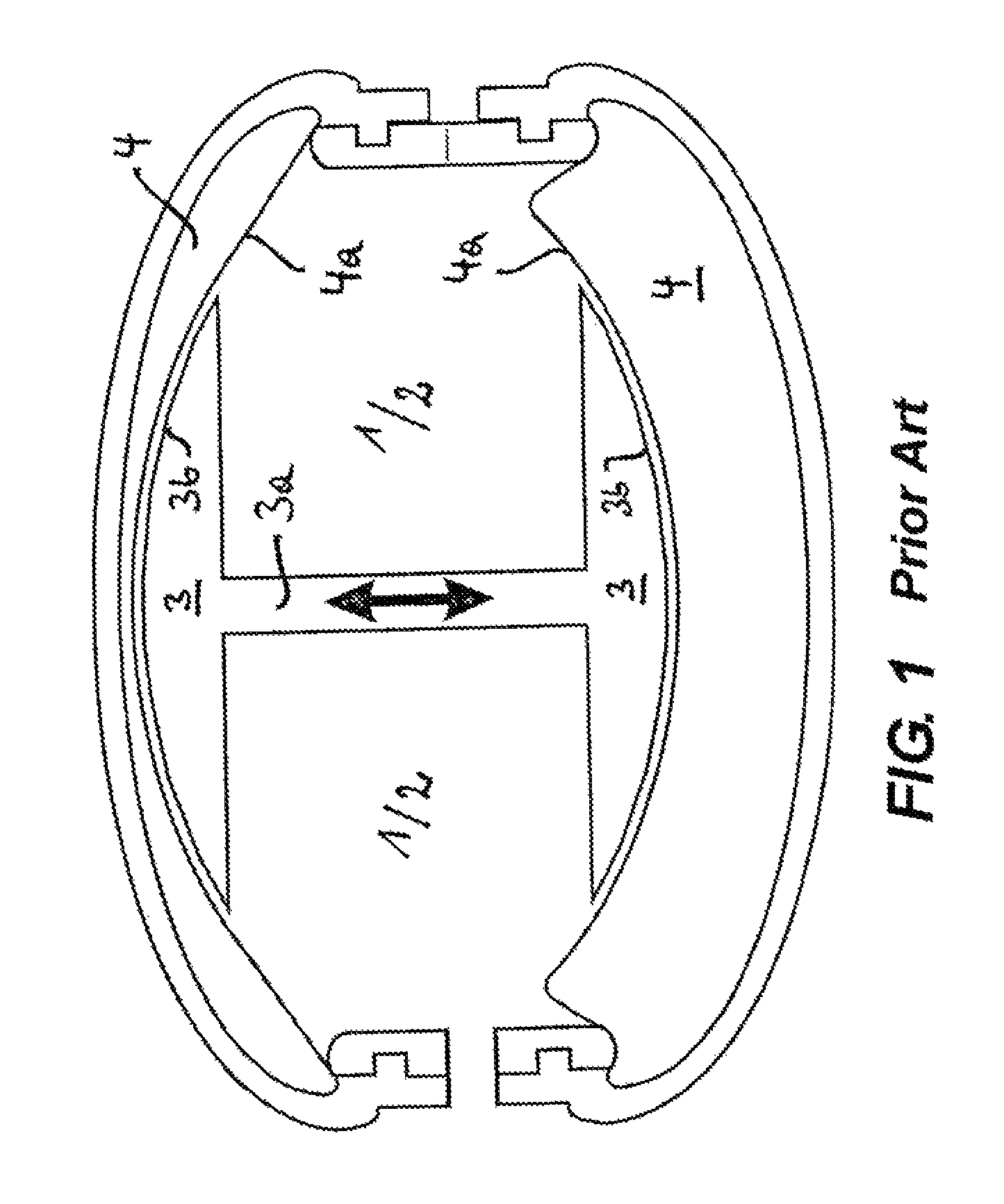
The concept as in Yeakley (U.S. Pat. No. 6,194,796) uses this leakage flux by utilizing only one coil, but this long coil leads to high ohmic losses, significantly reducing the degree of effectiveness.
Likewise, in these concepts, the high speeds of rotation of the rotors are a disadvantage, in that high shear forces are exerted upon the blood that lead to increased damage of the blood.
Concepts as in Vitale (U.S. Pat. No. 6,190,409 B1) are in a position to recreate the pumping process of the human heart in its pumping capacity, however, as the result of the revolving motor within the pump, the course of the pressure stream and volume stream of the blood cannot be sufficiently recreated as in the human heart.
As no compressible medium (e.g. air) is present in the system, the membrane is actively aspirated in the diastolic phase (filling phase), as a result of which a hemodynamically unfavorable collapse of the atrium can occur.
The many movable parts create, however, a higher level of noise and increased wear.

Method used


Image

  • Linear drive and pump system, in particular an artificial heart
  • Linear drive and pump system, in particular an artificial heart
  • Linear drive and pump system, in particular an artificial heart

Examples


first embodiment

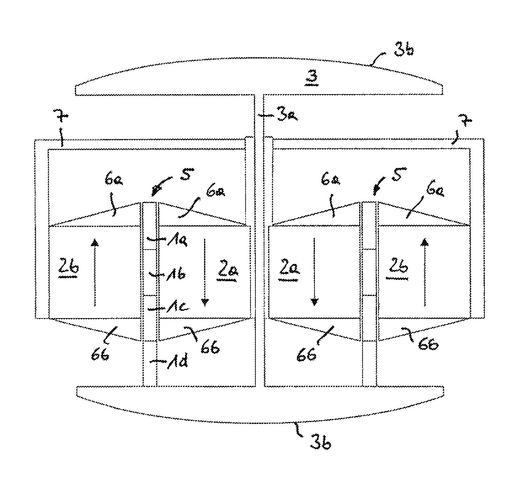
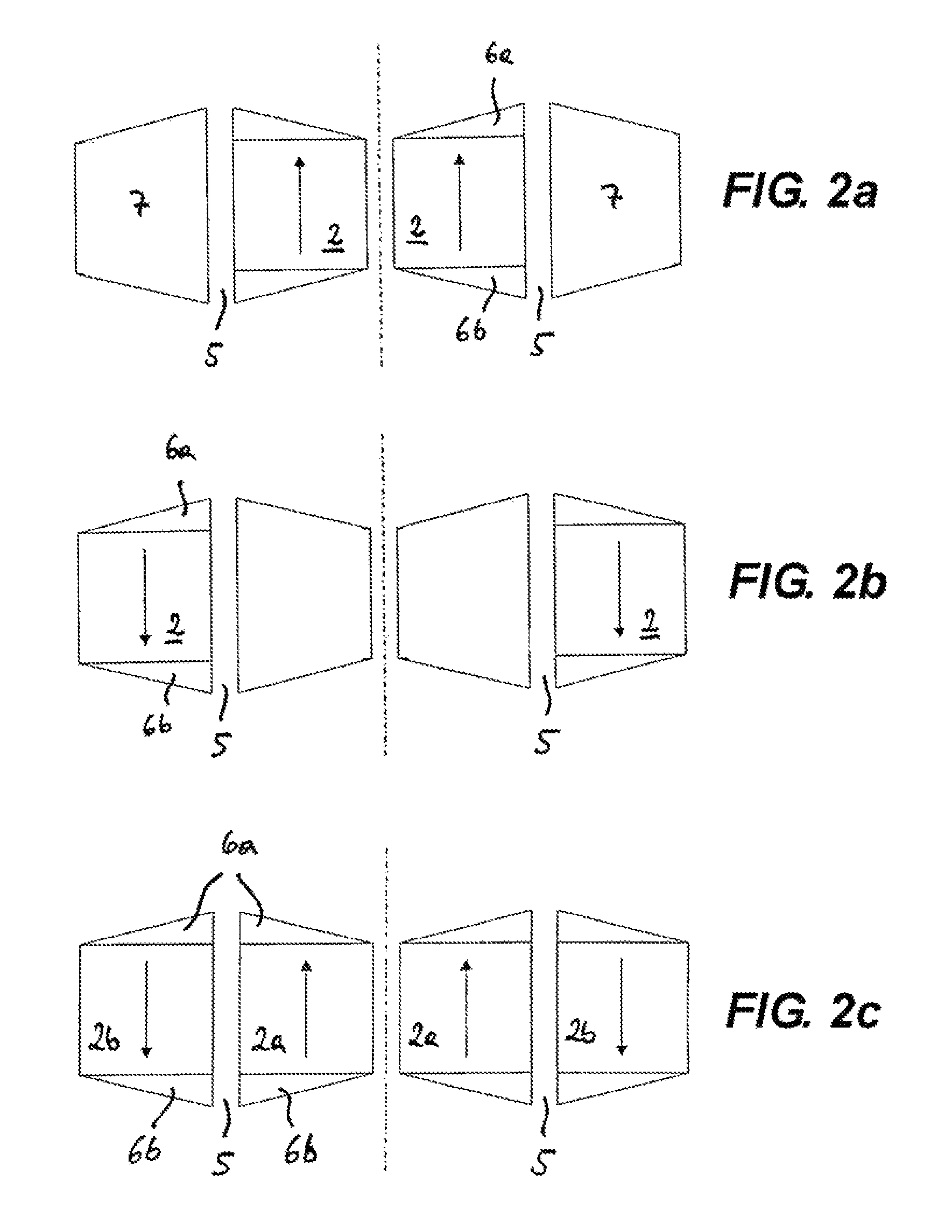
[0066]FIGS. 2a-2c show various variants of the invention.

[0067]In FIG. 2a an axially polarized permanent magnet 2 is coaxially inside relative to an air gap 5. The permanent magnet materials are shown by arrows and the direction of magnetization are indicated by the directions of the arrows. Here, the permanent magnet 2 is annular with an axial aperture through which, for example, a force-transmission element 3 can be passed and at which the corresponding bearing for the force-transmission element can be realized. Neither is shown here in the interest of simplifying the view. The dotted line shows a symmetry axis in FIGS. 2a-2c, especially a rotation-symmetry axis that is shown in FIGS. 3 and 4.

[0068]On the two axial (here upper and lower) ends of the permanent magnet pole shoes 6a and 6b (FIG. 3), in particular of frame-shaped or annular pole cross section are provided and firmly connected with the permanent magnet 2 in order to radially redirect the axial magnetic field of the per...


PUM


Abstract

The invention relates to an electrical linear drive, in particular for a pump system of an artificial heart, with a movable part and a stationary part, wherein the stationary part is formed by a permanent magnet arrangement and the movable part is formed by a coil arrangement, or vice versa, and wherein the coil arrangement and the permanent magnet arrangement can be moved to and fro relative to each other in an axial direction by means of current passed through the coil arrangement. The invention further relates to an electrical linear drive of this kind in which the permanent magnet arrangement is designed as a stack of frame-shaped, in particular ring-shaped magnets, which are magnetized alternately radially and axially in the axial direction, such that the magnetic field is strengthened on one side of the frame.

Description

CROSS REFERENCE TO RELATED APPLICATIONS[0001]This application is the US national stage of PCT application PCT / EP2008 / 006762, filed 18 Aug. 2008, published 26 Feb. 2009 as WO2009 / 024308, and claiming the priority of German patent application 102007039014.0 itself filed 17 Aug. 2007.FIELD OF THE INVENTION[0002]The invention concerns an electrical linear drive, in particular for a pump of an artificial heart with a movable and a stationary part, wherein the stationary part is formed by a permanent-magnet assembly and the movable part is formed by a coil assembly or vice versa, and the coil assembly and the permanent-magnet assembly can be moved to and fro relative to each other axially by current passing through the coil assembly. The invention further relates to a pump with such a drive, in particular an artificial heart for intracorporal or extracorporal assistance or the replacement of organs, in particular the heart.BACKGROUND OF THE INVENTION[0003]To the extent characteristics of ...

Claims


Application Information

Patent Timeline
IPC IPC(8): A61M1/10
CPCA61M1/1046F04B15/00F04B17/04H02K41/031A61M1/1055A61M1/12H02K1/27A61M60/898A61M60/148A61M60/422A61M60/196
Inventor FINOCCHIARO, THOMASBUTSCHEN, THOMASLESSMANN, MARCHAMEYER, KAYSCHMITZ-RODE, THOMASSTEINSEIFER, ULRICHKWANT, PAUL BARTELD
Owner RWTH AACHEN UNIVERSITY
Learn More