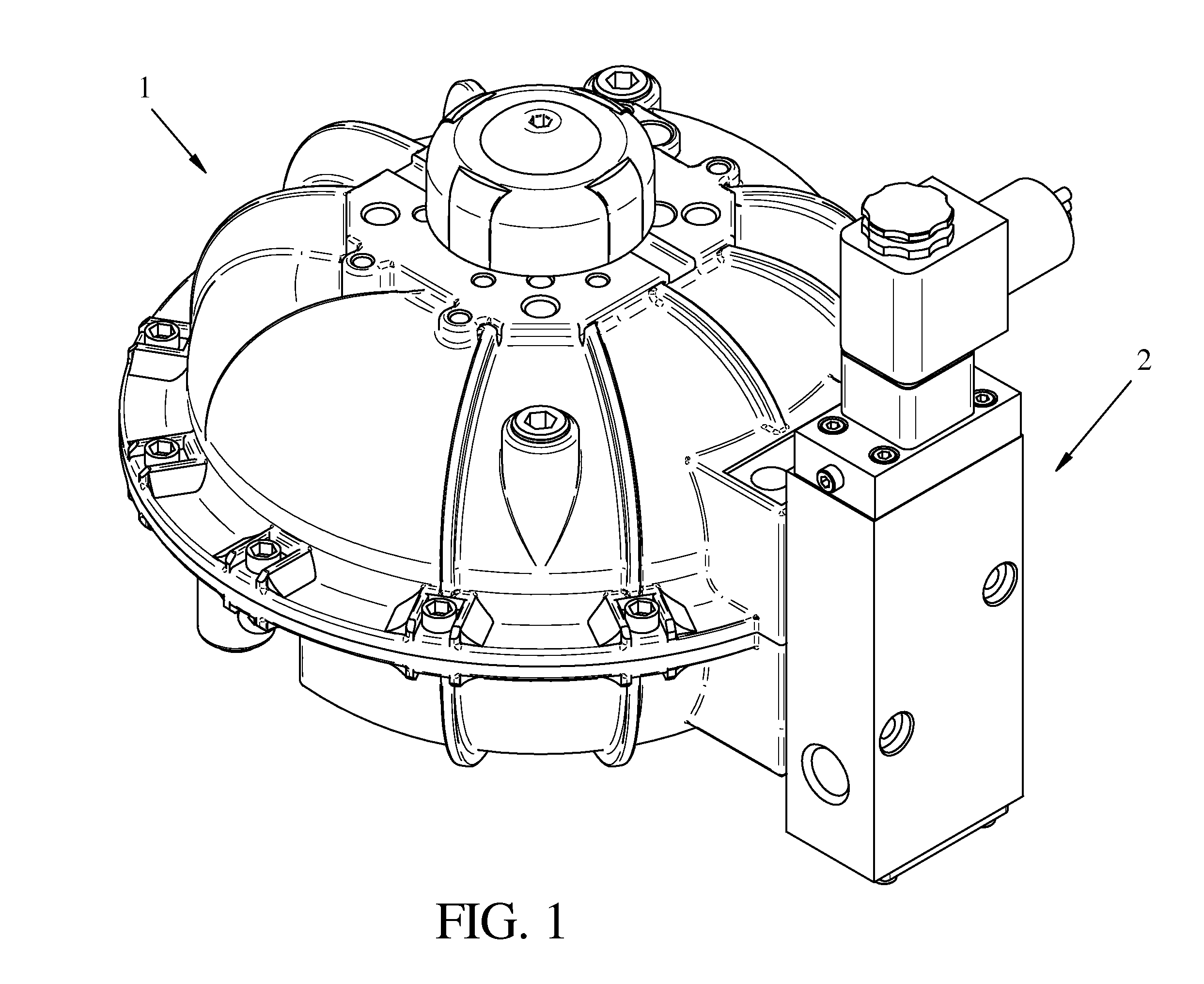
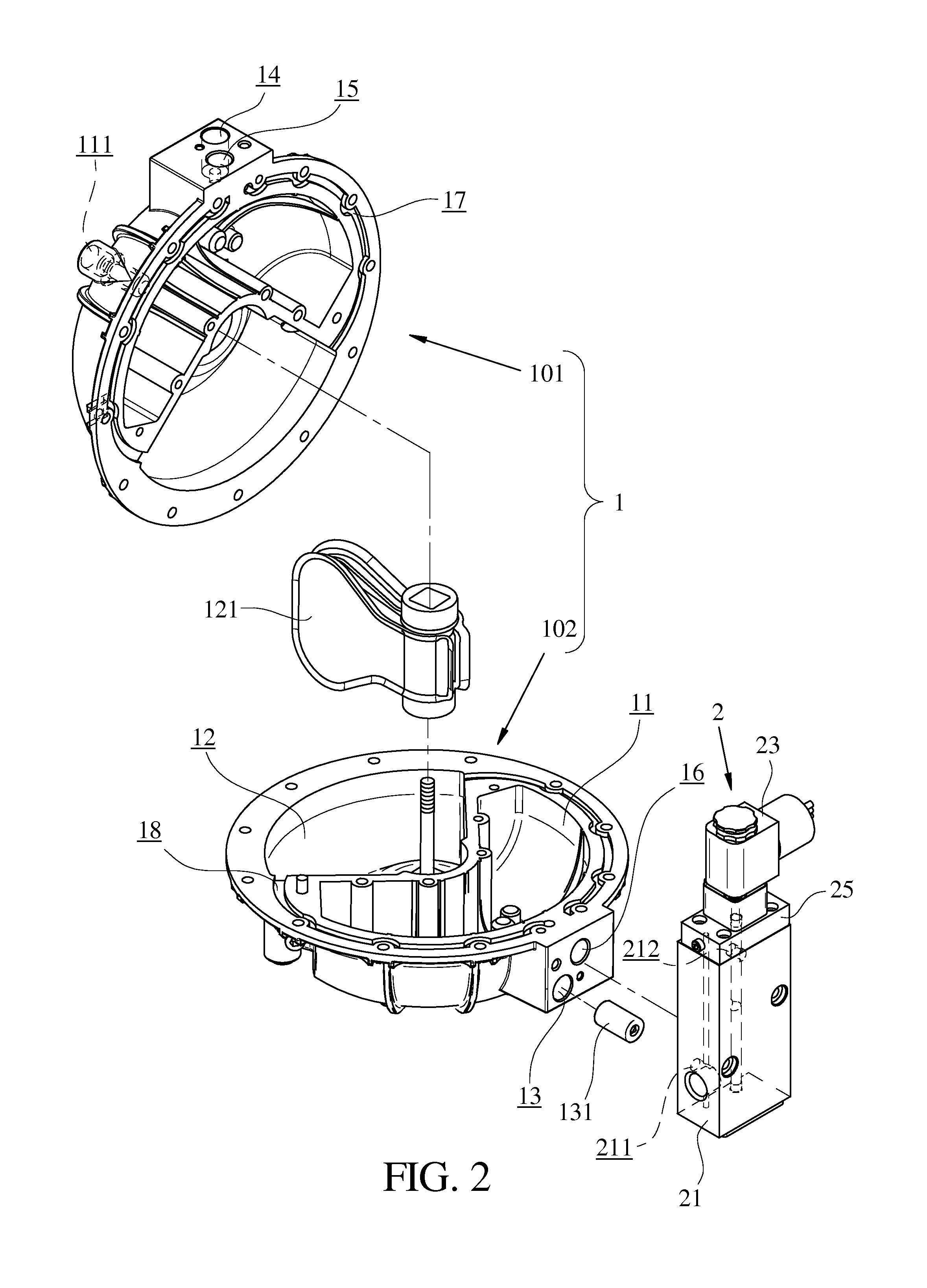
Pneumatic actuator air flow control system

a pneumatic actuator and air flow control technology, applied in the direction of valve operating means/releasing devices, machines/engines, mechanical equipment, etc., can solve the problems of increasing production and inventory costs, increasing packaging space, and increasing total production and inventory costs. , to achieve the effect of improving functions, increasing costs, and increasing maintenance frequency and complexity

Active Publication Date: 2013-11-05
EASYTORK AUTOMATION CORP
View PDF4 Cites 8 Cited by
  • Summary
  • Abstract
  • Description
  • Claims
  • Application Information

AI Technical Summary

Benefits of technology

[0005]Comparing with conventional techniques, the pneumatic actuator air flow control system in the present invention utilizes the solenoid air flow control valve to quickly switch between the double-acting and fail-safe operations depending on different user circumstances, which improves the functions of both single-acting and double-acting actuators, especially under different circumstances it does not need external installation of a declutchable manual gear operator or external piping for emergency manual override operation, which may lead to more costs, higher maintenance frequency and complexity. Through this invention the same actuator can be used for both fail-safe and double-acting functions. From manufacturing companies' perspective there is no need to invest heavily in multiple model lines, and on the other hand distributors do not need to invest more to buy both single-acting and double-acting actuators, so the inventory concern is reduced.

Problems solved by technology

But the disadvantage is the packaging occupies more spaces and the total cost is higher.
If they cannot provide a single product that can perform both double-acting and fail-return functions, the total production and inventory costs will increase accordingly.

Method used


Image

  • Pneumatic actuator air flow control system
  • Pneumatic actuator air flow control system
  • Pneumatic actuator air flow control system

Examples


Embodiment Construction

[0021]The detailed description set forth below is intended as a description of the presently exemplary device provided in accordance with aspects of the present invention and is not intended to represent the only forms in which the present invention may be prepared or utilized. It is to be understood, rather, that the same or equivalent functions and components may be accomplished by different embodiments that are also intended to be encompassed within the spirit and scope of the invention.

[0022]Unless defined otherwise, all technical and scientific terms used herein have the same meaning as commonly understood to one of ordinary skill in the art to which this invention belongs. Although any methods, devices and materials similar or equivalent to those described can be used in the practice or testing of the invention, the exemplary methods, devices and materials are now described.

[0023]All publications mentioned are incorporated by reference for the purpose of describing and disclos...


PUM


Abstract

A pneumatic actuator air flow control system includes a pneumatic rotary actuator (PRA) and a solenoid air flow control valve (SAFCV). The PRA contains an air reservoir and a vane housing allowing pressurized air to rotate an air-driven vane. The SAFCV includes a flow control valve body (FCVB), a pilot solenoid valve (PSV) and a switch system, wherein the FCVB and the PRA can be connected to direct the pressurized air into the air reservoir, and the PSV is used to control the pressurized air in and out of the PRA to change the vane's rotation movement in the vane housing. Additionally, the switch system allows users to switch between a double-acting and fail-safe operation. When there is no pressurized air and / or electrical power and if an emergent need to open or close the valve, a manual override in the PSV can be used without further installation of a declutchable manual gear operator or external piping when there is no pressurized air and / or electrical power.

Description

FIELD OF THE INVENTION[0001]The present invention provides a pneumatic actuator air flow control system, specifically this technology providing a pneumatic rotary actuator and a solenoid air flow control valve which allows easily switching between a double-acting and a fail-safe model. It also provides an emergency manual override operation without an external installation of a declutchable manual gear operator (gear box) or external piping in the event of no pressurized air and / or electrical power.BACKGROUND OF THE INVENTION[0002]Currently, there are many kinds of actuator designs which use pressure or torque to force the rotation of the shaft in the actuator (in both clockwise and counterclockwise manners) to drive the rotary valve to open and close, and further control the on / off position of the valve in a pipeline. There are two types of pneumatic rotary actuators: single-acting and double-acting. The single-acting actuator is used on the valve that requires fail-return and trad...

Claims


Application Information

Patent Timeline
Patent Type & Authority Patents(United States)
IPC IPC(8): F16K31/12F16K31/44F15B13/044F01C9/00
CPCF15B15/12F15B20/004
Inventor WANG, JAMES
Owner EASYTORK AUTOMATION CORP
Why Eureka
Try Eureka