
Heat transfer tube support structure

a technology of heat transfer tube and support plate, which is applied in the direction of lighting and heating apparatus, greenhouse gas reduction, and steam generation using hot heat carriers, etc., can solve the problems of dents and scratches on the heat transfer tubes, and large amount of load applied to the heat transfer tubes. , to achieve the effect of preventing deterioration of reliability and durability of heat transfer tubes

Active Publication Date: 2013-11-05
MITSUBISHI HEAVY IND LTD
View PDF25 Cites 1 Cited by
  • Summary
  • Abstract
  • Description
  • Claims
  • Application Information

AI Technical Summary

Benefits of technology

This design prevents dents and scratches on heat transfer tubes by dispersing loads and reducing the volume of tube holes, thereby enhancing the reliability and durability of the tubes and maintaining structural strength.

Problems solved by technology

Further, when the attitude of the steam generator is changed in the manufacturing process, external force is applied to the steam generator due to the change of the attitude and further the direction in which the own weight of the steam generator is applied thereto changes, thereby strain also occurs in the tube support plates.
Accordingly, there is a possibility that dents and scratches occur to the heat transfer tube depending on a magnitude of strain occurred to the tube support plate.
Accordingly, even if the inner surface of the tube hole slightly inclines, the one open end of the tube hole is greatly dislocated from the other open end thereof, thereby a large amount of load is applied to the heat transfer tube.
Occurrence of the dents and the scratches to the heat transfer tube as described above is not preferable because the reliability and the durability of the heat transfer tube are diminished.

Method used


Image

  • Heat transfer tube support structure
  • Heat transfer tube support structure
  • Heat transfer tube support structure

Examples


first embodiment

[0061]A first embodiment of the present invention will be explained below with reference to the drawings.

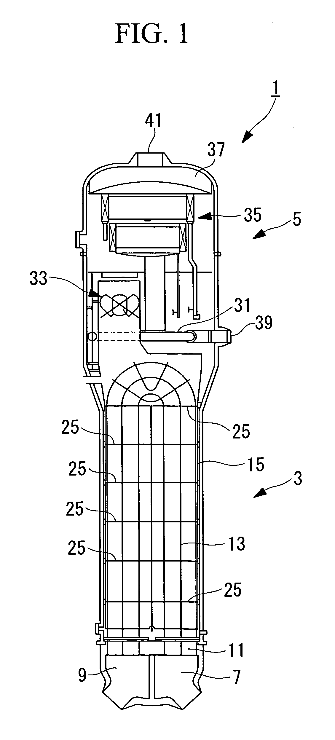
[0062]The embodiment shows an example in which a heat transfer tube support structure according to the present invention is applied to a steam generator 1 shown in FIG. 1.

[0063]The steam generator 1 generates high pressure steam for driving a power generation turbine in a pressurized water reactor power station by carrying out heat exchange between high temperature / high pressure primary coolant water (primary coolant medium), which has collected the heat generated in a reactor core of an atomic reactor and secondary coolant water (secondary coolant medium) which flows in a flow path arranged independently of that of the primary coolant water to thereby boil the secondary coolant water.

[0064]A specific arrangement of the steam generator 1 will be explained below.

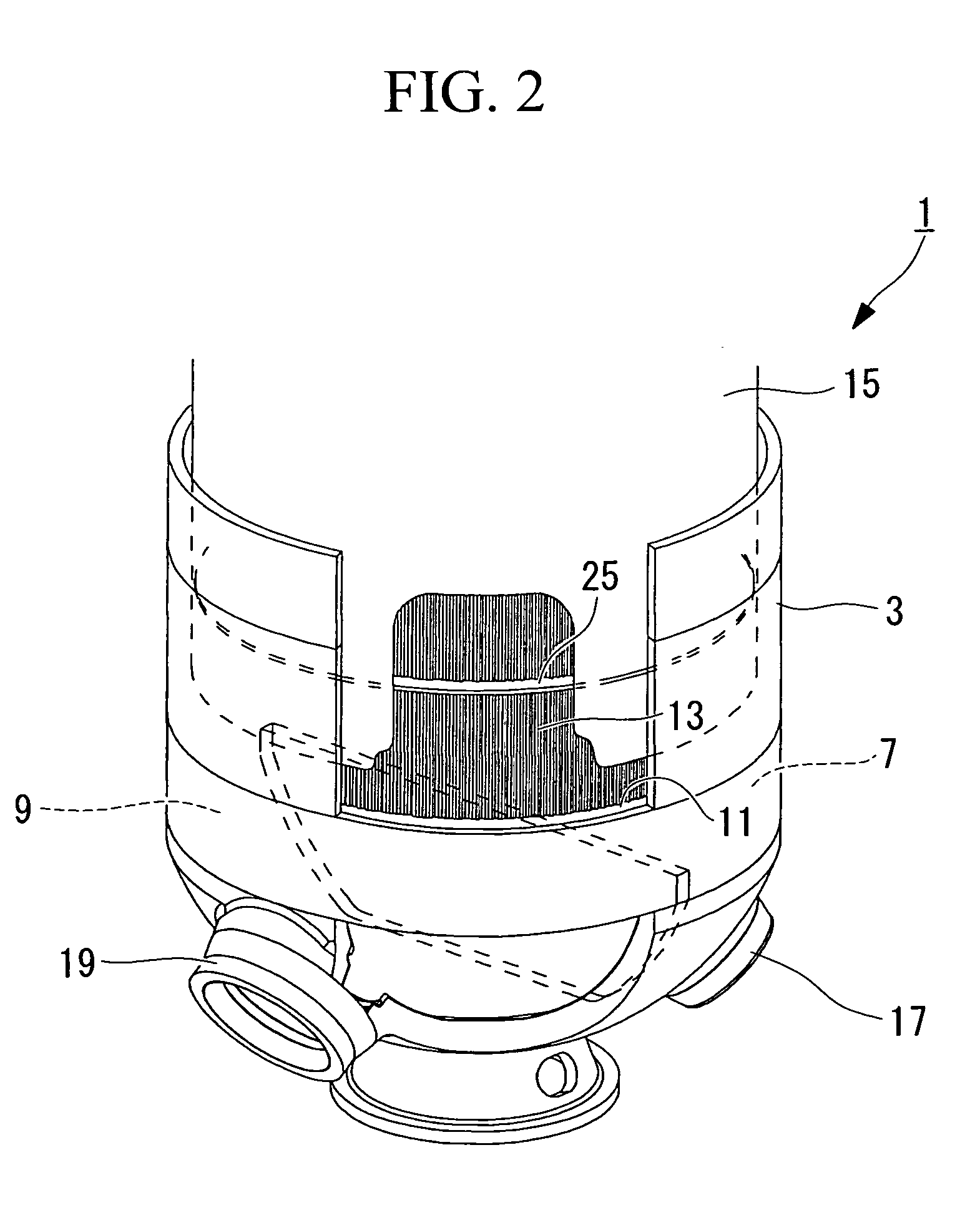
[0065]As shown in FIGS. 1 and 2, the steam generator 1 has a vessel composed of an approximately cylindrical-shaped lowe...

second embodiment

[0102]A second embodiment of the present invention will be explained below using FIG. 11.

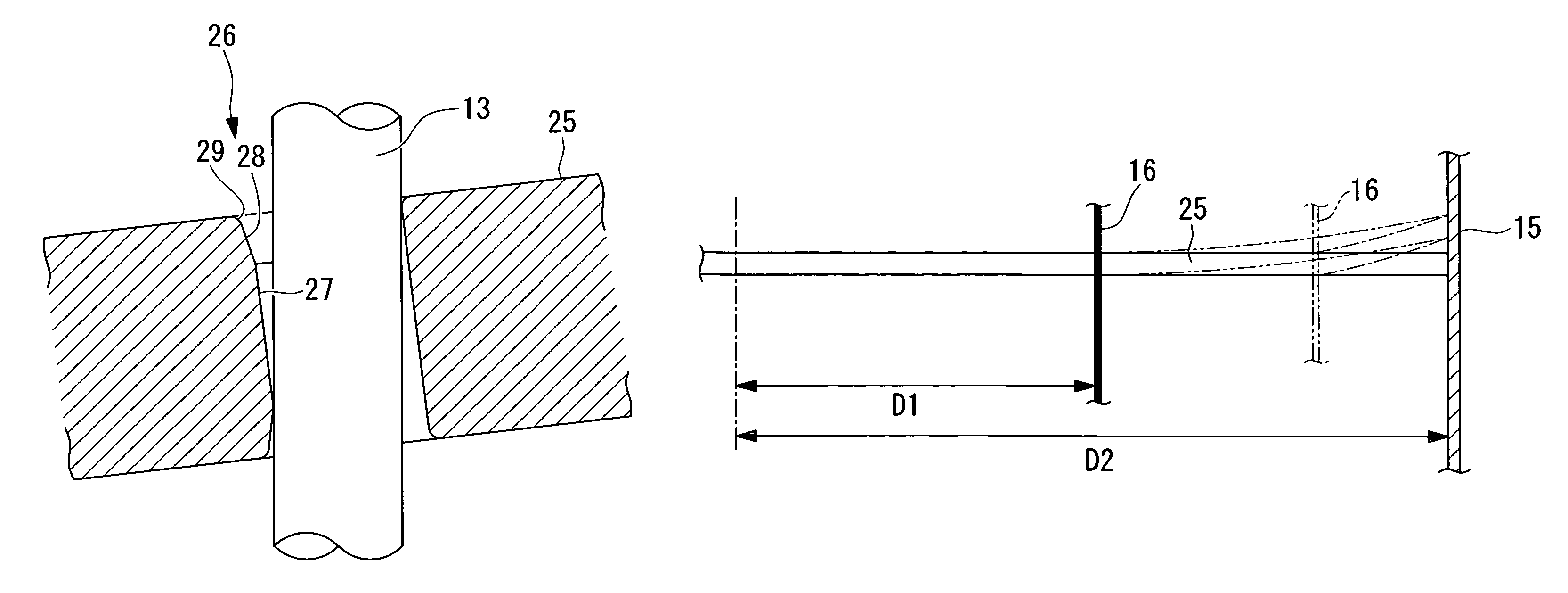
[0103]A heat transfer tube support structure according to the second embodiment is arranged in the steam generator 1 shown in the first embodiment such that when the distance from the support position of the tube support plate 25, which is located nearest to the peripheral edge of the tube support plate 25 in the support positions of the tube support plate 25 supported by the stay rods 16 (inner peripheral portion support members), to the center position of the tube support plate 25 is shown by D1, and the distance from the support position of the tube support plate 25 supported by the wrapper 15 (peripheral edge support member) to the center position of the tube support plate 25 is shown by D2, a relation of D1 / D2<0.6 is established.

[0104]The lower barrel 3 of the steam generator 1 is formed by welding a cylindrical barrel portion to a dome-shaped channel head for closing the lower end of the b...


PUM


Abstract

An object is to provide a heat transfer tube support structure capable of preventing deterioration of the reliability and the durability of a heat transfer tube. In a steam generator (heat exchanger) having a lower barrel (vessel), heat transfer tubes disposed in the lower barrel, and tube support plates disposed in the lower barrel and having heat transfer tube insertion holes opened in a thickness direction, support portions for supporting the heat transfer tubes are formed to the intermediate portions of the inner surfaces of the heat transfer tube insertion holes in the axial direction of the heat transfer tube insertion holes, and the regions between the support portions and the respective open ends of the heat transfer tube insertion holes are formed of inclined surfaces inclining in a radial direction outwardly in the heat transfer tube insertion holes toward the open ends, respectively.

Description

TECHNICAL FIELD[0001]The present invention relates to a heat transfer tube support structure in a heat exchanger of a steam generator and the like used in, for example, a nuclear power plant.BACKGROUND ART[0002]There is a heat exchanger including a vessel, a plurality of heat transfer tubes disposed in the vessel, and tube support plates for supporting the heat transfer tubes in the vessel. In the heat exchanger, heat is exchanged between a primary coolant water and a secondary coolant water in such a manner that the primary coolant water is caused to flow in the heat transfer tubes as well as the secondary coolant water is caused to flow in the vessel.[0003]Here, a wrapper (peripheral edge support member) for supporting the peripheral edges of the tube support plates and stay rods (inner peripheral portion support members) for supporting the inner peripheral portions of the tube support plates are disposed in the vessel, and the tube support plates are fixed by these members in the...

Claims


Application Information

Patent Timeline
Patent Type & Authority Patents(United States)
IPC IPC(8): F28F9/00F28F9/04
CPCF22B1/162F22B37/204F28D7/06F28F9/0131Y02E30/00F28F9/013F22B1/16G21D1/00F22B37/20
Inventor INOUE, TOMOYUKIOGAWA, NAOKIHIRANO, HIROSHISHIOTA, MASAO
Owner MITSUBISHI HEAVY IND LTD
Learn More