Tiltable MEMS mirror

a mems mirror and mirror technology, applied in the field of mems mirrors, can solve the problems of increasing the sensitivity of mems mirrors to shock and vibration, increasing the mass and moment of inertia, and a new problem to occur, so as to reduce the quality of optical beams reflected

Active Publication Date: 2013-10-01
LUMENTUM OPERATIONS LLC
View PDF10 Cites 5 Cited by
  • Summary
  • Abstract
  • Description
  • Claims
  • Application Information

AI Technical Summary

Benefits of technology

[0010]In the present invention, it is recognized that it is the mirror edges that contribute the most to the moment of inertia (rotational inertia), while it is generally the mirror center that contributes the most to a reduction of the quality of an optical beam reflected from the mirror. This is because the local intensity of an optical beam is typically the highest at the beam center, and the beam center is usually aligned to the mirror center. Accordingly, by providing a mirror having laterally varying thickness matched to the local variation of the intensity of the optical beam, the quality of the latter may be preserved while the moment of inertia of the mirror may be significantly reduced.
[0011]In accordance with the invention there is provided a MEMS mirror device including a substrate, a MEMS mirror having a top reflective surface and a profiled bottom surface, and a hinge extending from the MEMS mirror enabling the MEMS mirror to pivot about a tilt axis above the substrate. The MEMS mirror is absent any voids or ribs. It has a longitudinal central axis perpendicular to the tilt axis and crossing the tilt axis at a first point, with first and second ends being disposed on the longitudinal axis at the outer free ends of the MEMS mirror. The profiled bottom surface is such that the MEMS mirror thickness, between the top and bottom surfaces, decreases in going from the first point towards the first and the second ends of the MEMS mirror, for reducing a moment of inertia of the MEMS mirror about the tilt axis.
[0016](b) profiling the bottom surface of the mirror wafer, so as to cause the MEMS mirror to have thickness decreasing in going from the first point towards the first and the second ends for reducing a moment of inertia of the MEMS mirror about the tilt axis.
[0018]In accordance with another aspect of the invention, there is further provided a method of manufacturing a MEMS optical switch for switching an optical beam having a laterally varying intensity, comprising manufacturing a MEMS mirror having the thickness correlated with the beam intensity variation, whereby the moment of inertia of the manufactured MEMS mirror is lessened while keeping a pre-defined quality of the switched optical beam, so as to ensure a pre-defined extinction ratio and insertion loss of the MEMS optical switch.

Problems solved by technology

Increased thickness of MEMS micromirrors, however, causes another problem to occur.
The problem is related to dynamic performance of MEMS micromirrors.
Furthermore, increased mass and moment of inertia increases sensitivity of MEMS mirrors to shock and vibration.
However, increasing the stiffness of hinges requires increasing electrostatic torque created by MEMS actuators to offset the increased spring force of stiffer hinges.
Unfortunately, there is a limit to a magnitude of the torque that can be generated, due to geometrical and electronic driver limitations.
One drawback of the ribs and honeycomb-reinforced MEMS micromirror structures of the prior art is the difficulty of manufacturing complex three-dimensional structures.
For example, the honeycomb structure of Moidu, although providing a very good stiffness to rotational inertia ratio, requires multiple wafer stacked together to form the honeycomb core and skins, thus increasing manufacturing complexity and cost.

Method used


Image

  • Tiltable MEMS mirror
  • Tiltable MEMS mirror
  • Tiltable MEMS mirror

Examples


Embodiment Construction

[0029]While the present teachings are described in conjunction with various embodiments and examples, it is not intended that the present teachings be limited to such embodiments. On the contrary, the present teachings encompass various alternatives, modifications and equivalents, as will be appreciated by those of skill in the art.

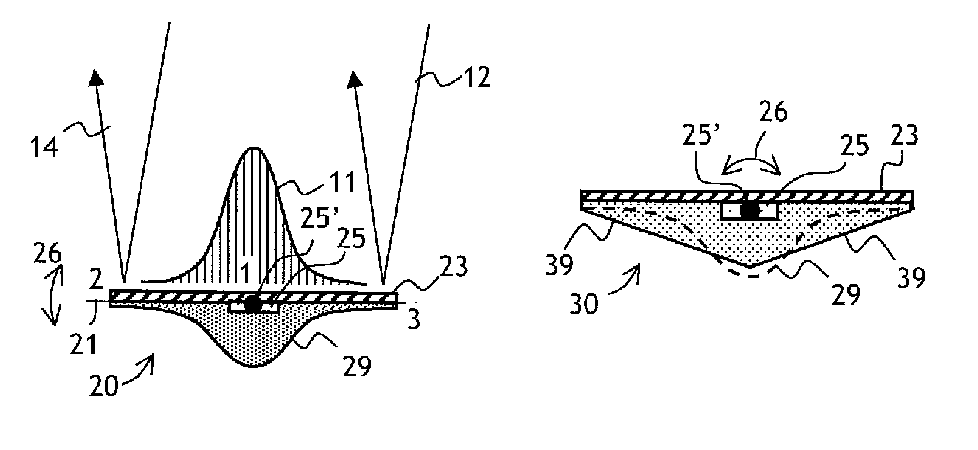
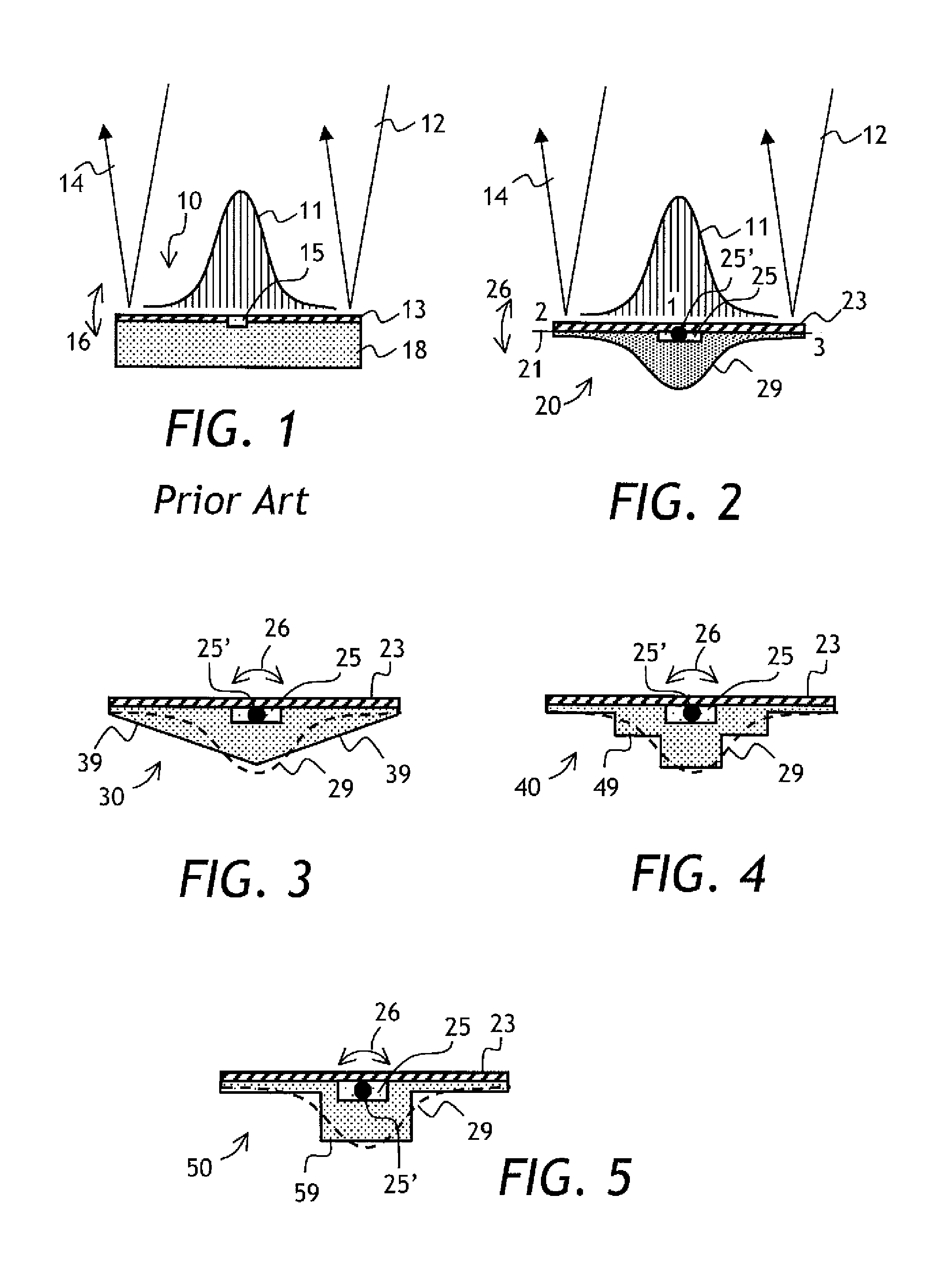
[0030]Referring now to FIG. 1, an optical beam 12 having a spatial intensity distribution 11 impinges on a conventional flat MEMS mirror 10 having a substrate 18 supporting a reflective coating 13. The optical beam 12 reflects from the reflective coating 13, as shown at 14. The MEMS mirror 10 has a torsional hinge 15 for tilting the MEMS mirror 10 as shown by arrows 16, thus steering the reflected optical beam 14. The MEMS mirror 10 has a uniform thickness.

[0031]The reflective coating 13 of the MEMS mirror 10 typically has a non-zero curvature due to residual stresses, or thermally induced stresses in the reflective coating 13 due to thermal mismatch with...


PUM


Abstract

A MEMS mirror is disclosed having thickness correlated with the intensity profile of an impinging optical beam, so as to reduce moment of inertia of the MEMS mirror while preserving optical quality of the reflected beam. It is the mirror edges that contribute the most to the moment of inertia, while it is generally the mirror center that contributes the most to a reduction of the quality of an optical beam reflected from the mirror. Accordingly, by providing a mirror having laterally varying thickness matched to the local variation of the intensity of the optical beam, the quality of the latter may be preserved while the moment of inertia of the mirror may be significantly reduced. The thickness of MEMS mirrors may be varied continuously or stepwise; in one direction or in two mutually orthogonal directions.

Description

CROSS-REFERENCE TO RELATED APPLICATIONS[0001]The present invention claims priority from U.S. Provisional Patent Application No. 61 / 289,473, filed Dec. 23, 2009, which is incorporated herein by reference.TECHNICAL HELD[0002]The present invention relates to micro-electro-mechanical (MEMS) devices, and in particular to tiltable MEMS mirrors for redirecting beams of light.BACKGROUND OF THE INVENTION[0003]Micro-electro-mechanical systems (MEMS) arc increasingly used in optical switching and scanning applications. Visual displays based on switchable MEMS micromirrors capable to withstand billions of switching cycles are now common. Using MEMS devices in fiberoptic switches attracts a particular interest. Light emitted by optical fibers can be tightly focused, which facilitates utilization of MEMS micromirrors to reliably switch optical signals between different optical fibers or waveguides.[0004]In recent years, multiport wavelength-selective optical switches have been used to provide wav...

Claims


Application Information

Patent Timeline
Patent Type & Authority Patents(United States)
IPC IPC(8): G02B26/08
CPCG02B26/0841G02B26/10G02B26/105
Inventor MOIDU, ABDUL JALEEL K.
Owner LUMENTUM OPERATIONS LLC
Why Eureka
Try Eureka