
Multi-stable actuation apparatus and methods for making and using the same

a multi-stable, actuator technology, applied in the direction of valve details, valve arrangement, hot gas positive displacement engine plants, etc., can solve the problems of electromechanical solenoids, unsatisfactory needs, and general power requirements of solenoid actuators, so as to reduce operating costs, less ecologically damaging waste, and cost-effective

Inactive Publication Date: 2013-09-24
AUTOSPLICE SYST
View PDF18 Cites 16 Cited by
  • Summary
  • Abstract
  • Description
  • Claims
  • Application Information

AI Technical Summary

Benefits of technology

[0021]In a fifth aspect of the invention, business methods associated with the aforementioned actuator apparatus is disclosed. In one exemplary embodiment, the business method comprises selling the bistable SMA actuator apparatus as a replacement part, thereby reducing energy usage in extant valve installations.
[0024]In a seventh aspect, a more cost effective and ecologically friendly (“green”) battery-powered actuator is disclosed. In one embodiment, the actuator utilizes a parallel battery arrangement which will operate even with one or more failed batteries. Especially when used in conjunction the power-efficient actuator referenced above, this parallel arrangement necessitates fewer battery replacements during the same period of time, thereby reducing operating costs and producing less ecologically damaging waste.

Problems solved by technology

A common limitation with regards to electromechanical solenoids (particularly those that are used in small or portable consumer applications such as the aforementioned automatic flush toilets) is the fact that the actuating current is often generated via a series of batteries.
These solenoid actuators generally have comparatively large power requirements, and are often inefficient due to inter alia the internal resistance associated with the application of an electric current across the solenoid coils.
Despite the foregoing wide variety of actuation approaches and configurations in the prior art, there remains an unsatisfied need for improved actuator apparatus that: (i) utilizes a more reliable power source than a typical “series” battery arrangement, (ii) reduces overall power requirements for operation, (iii) reduces power necessary for linear movement initiated by the actuator, and (iv) reduces internal resistance and Ohmic power losses.

Method used


Image

  • Multi-stable actuation apparatus and methods for making and using the same
  • Multi-stable actuation apparatus and methods for making and using the same
  • Multi-stable actuation apparatus and methods for making and using the same

Examples


Embodiment Construction

[0055]Reference is now made to the drawings wherein like numerals refer to like parts throughout.

[0056]As used herein, the terms “electrical component” and “electronic component” are used interchangeably and refer to components adapted to provide some electrical or electronic function, including without limitation, fuses, transformers, filters, inductors, capacitors, resistors, operational amplifiers, transistors and diodes, whether discrete components or integrated circuits, whether alone or in combination. In addition, other ancillary electronic devices such as for example, so-called EMI shields and the like, which could be considered passive in nature, are considered encompassed as possibilities within the meaning of this term.

[0057]As used herein, the term “filament” refers to any substantially elongate body, form, strand, or collection of the foregoing, including without limitation drawn, extruded or stranded wires or fibers, whether metallic or otherwise.

[0058]As used herein, ...


PUM


Abstract

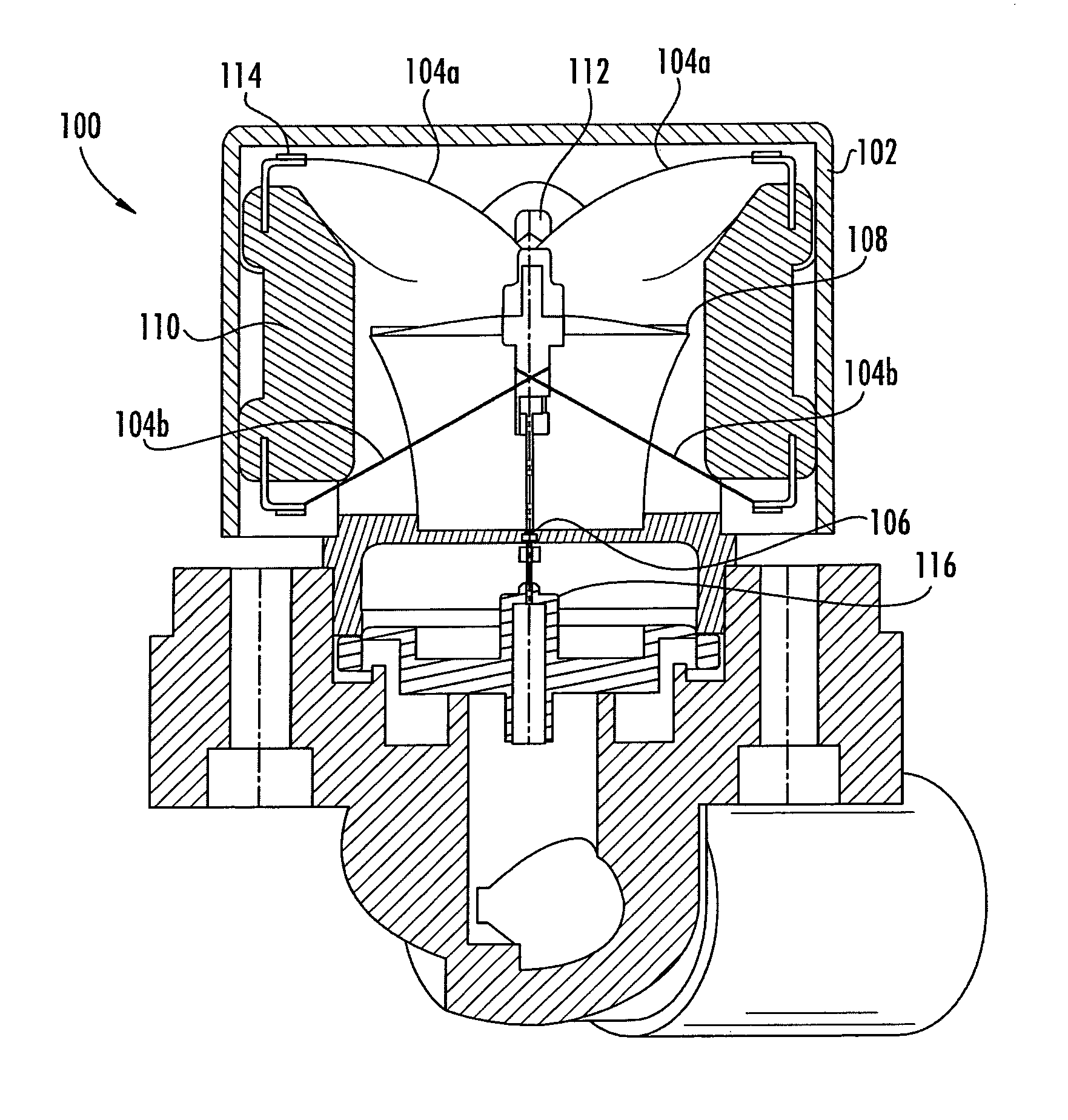
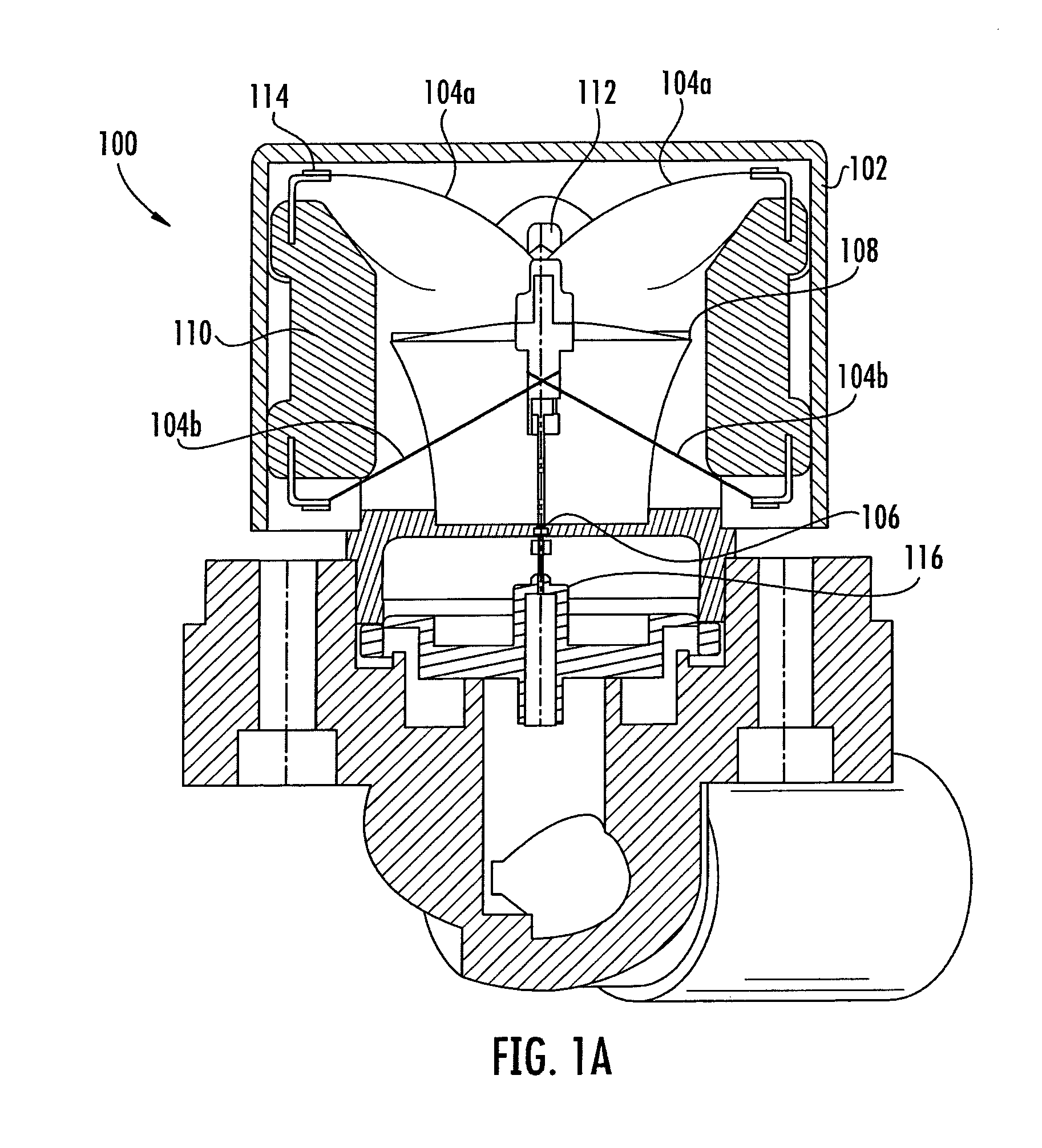
Actuator apparatus having a multi-stable element actuated by memory alloy actuating elements. In one embodiment, the multi-stable actuator comprises a bistable (two-state) diaphragm element adapted to alternate between two stable configurations via forces exerted on the diaphragm by more than one memory alloy filaments in response to thermal activation. In another embodiment, the bistable diaphragm of the multi-stable actuator transitions from a first to a second stable configuration via forces exerted by a single filament in response to direct or indirect thermal activation. A portion of the assembly is displaced when the assembly is in the second configuration. The bistable diaphragm transitions back to the first stable configuration via application of mechanical force on a portion of the assembly which was displaced. Methods for making and using the bistable actuator apparatus are also disclosed.

Description

PRIORITY APPLICATIONS[0001]This application claims priority to co-owned U.S. provisional patent application Ser. No. 61 / 189,148 filed Aug. 14, 2008 of the same title; as well as and co-owned U.S. Provisional Patent Application Ser. No. 61 / 206,883 filed Feb. 4, 2009 entitled “Memory Alloy-Actuated Apparatus and Methods for Making and Using the Same”, each of which is incorporated herein by reference in its entirety.COPYRIGHT[0002]A portion of the disclosure of this patent document contains material that is subject to copyright protection. The copyright owner has no objection to the facsimile reproduction by anyone of the patent document or the patent disclosure, as it appears in the Patent and Trademark Office patent files or records, but otherwise reserves all copyright rights whatsoever.1. FIELD OF THE INVENTION[0003]The present invention relates generally to the area of sensors, actuators and switches, and more specifically in one exemplary aspect, to an improved design for and me...

Claims


Application Information

Patent Timeline
Patent Type & Authority Patents(United States)
IPC IPC(8): F16K31/00
CPCF16K31/002F16K31/025
Inventor FOSHANSKY, LEONIDBOGURSKY, ROBERT
Owner AUTOSPLICE SYST
Learn More