
Minimally invasive instrument set, devices and related methods

a technology of minimally invasive instruments and instruments, applied in the field of minimally invasive instruments and devices, can solve the problems of large incisions, disruption or resection of significant soft tissue, long recovery time for patients, etc., and achieve the maximum line-of-sight potential of the surgeon, improve the fluoroscopic visualization of screws and rods, and facilitate the effect of screw fixing

Active Publication Date: 2013-09-17
DEPUY SYNTHES PROD INC
View PDF193 Cites 32 Cited by
  • Summary
  • Abstract
  • Description
  • Claims
  • Application Information

AI Technical Summary

Benefits of technology

The instrument set simplifies spine surgery by improving visualization, reducing tissue trauma, and shortening surgery time through easier instrument handling and reduced tool replacement, while maintaining strength during final tightening.

Problems solved by technology

Traditional spine surgeries were conducted utilizing an open procedure resulting in a relatively large incision, disruption or resection of significant soft tissue and long recovery times for patients.
However, the smaller incision or incisions diminish the line-of-sight for a surgeon to directly view a surgical site, because patient soft tissue often limits a surgeon's ability to view the surgical site.
Minimally invasive spine instruments utilized for such procedures can be difficult to assemble, limit a surgeons ability to view the surgical site, are bulky and extend a significant distance out of a patient's skin, may detach from the screws during the procedure, are complicated to operate involving many steps, result in procedures involving removal and replacement of multiple instruments, inhibit imaging utilizing a C-arm or Fluoroscope as a result of their size and material composition and may be difficult to detach from the screws at the conclusion of the procedure.
In addition, current minimally invasive fixation of screws and placement of rods in spine surgery often result in undesirable levels of trauma to a patient's soft tissue in and around the surgical site, along the surgical pathway and proximate the incision.
Once assembled for rod insertion, these conventional minimally invasive systems are typically locked into a predetermined position and inhibit a surgeon's options in adapting their surgical technique to a particular patient's anatomy or in adapting the instruments to implant the components in a manner that would benefit the patient.
Certain conventional, minimally invasive spine instrumentation for the placement of pedicle screws and rods is bulky and complicated to utilize with multiple tool exchanges and complicated steps in mounting, removing, aligning and otherwise manipulating the bulky instrumentation to secure screws in the vertebrae and fix the rod to the implanted screws.
A surgeon is often unable to directly visualize the surgical site, the screws and / or the rods once they are implanted in a patient, because of the bulky instruments and the relatively small size of the surgical incisions.
Accurate intra-operative visualization of the implant construct can be difficult for a spine surgeon to verify with fluoroscopy because the relatively bulky metallic instruments attached to the construct are radio-opaque.
In addition, the complicated procedures and instrumentation utilized with certain minimally invasive spine surgeries often require removal and replacement of different instruments through the enclosed cannulas or sleeves, thereby fatiguing a surgeon and extending the time that a patient is in surgery and subjected to anesthesia.
Further, complicated procedures and instrumentation can lead to surgical delays, particularly for newly trained or novice surgical staff and surgeons when deciphering the complicated procedures and instrumentation.
Further, the grasping handle of the counter-torque tool of conventional minimally invasive spine surgical sets can impede the surgeons visibility or prevent the use of other instruments during the procedure.
The screwdriver typically a self-retaining tip that has a limited ability to retain the locking cap if the sides of the sleeve or cannula are impacted with the locking cap, resulting in the locking cap becoming detached and falling into the incision, thereby requiring removal of the screwdriver and retrieval of the locking cap through the sleeve or cannula or through one of the minimal incisions.
Further, conventional minimally invasive instrument sets often have an unwieldy number of excess protruding parts proximate the incision, often for the purpose of fixing the retractor to the polyaxial bone screw, that can block the surgeon's view of the site.
Such unwieldy parts severely inhibit a surgeons ability to visualize the construct at the surgical site and result in generally blind insertion and significant reliance on the instrumentation.
Coupled with the metallic composition and bulky size of the instruments, visualization of the construct may not be possible until all of the instruments are removed from the construct and the incision at the conclusion of the procedure.
Subsequently, if the finally implanted construct is not acceptable to the surgeon, the bulky and unwieldy instruments may have to be reattached to the construct or the surgeon may need to repair the construct through an open procedure.
The conventional minimally invasive spine instruments are typically bulky and unwieldy to react forces encountered by the relatively long, hollow sleeves or cannulae during final tightening of the locking caps to the pedicle screws.
The hollow sleeves or cannulae are typically bulky and stiff specifically at the distal end portions to rigidly hold the arms of the pedicle screws in position during final tightening to prevent splaying of the pedicle screws under final tightening loads.
In addition, the hollow sleeve or cannulae are bulky and unwieldy along their length to prevent twisting, splaying or breakage during the final tightening step.

Method used


Image

  • Minimally invasive instrument set, devices and related methods
  • Minimally invasive instrument set, devices and related methods
  • Minimally invasive instrument set, devices and related methods

Examples


Embodiment Construction

[0040]Certain terminology is used in the following description for convenience only and is not limiting. The words “right,”“left,”“lower,” and “upper” designate directions in the drawings to which reference is made. The words “inwardly” or “distally” and “outwardly” or “proximally” refer to directions toward and away from, respectively, the geometric center or orientation of the exemplary instrument set and related parts thereof. The words, “anterior,”“posterior,”“superior,”“inferior,”“lateral,”“medial,” and related words and / or phrases designate exemplary positions and orientations in the human body to which reference is made and are not meant to be limiting. The terminology includes the above-listed words, derivatives thereof and words of similar import.

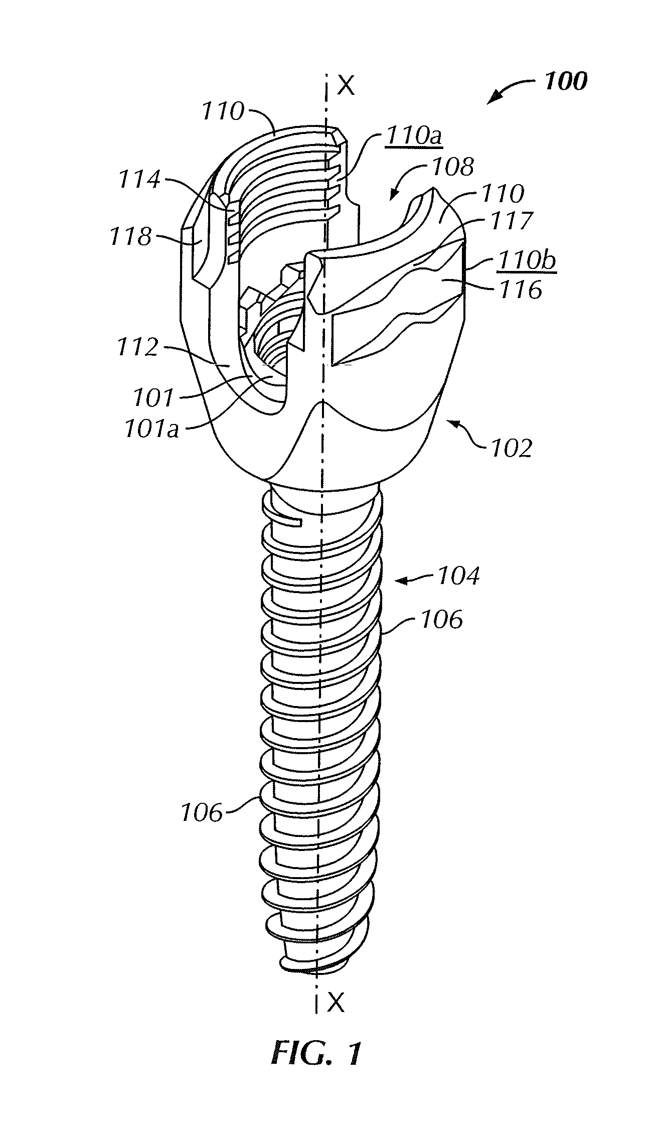
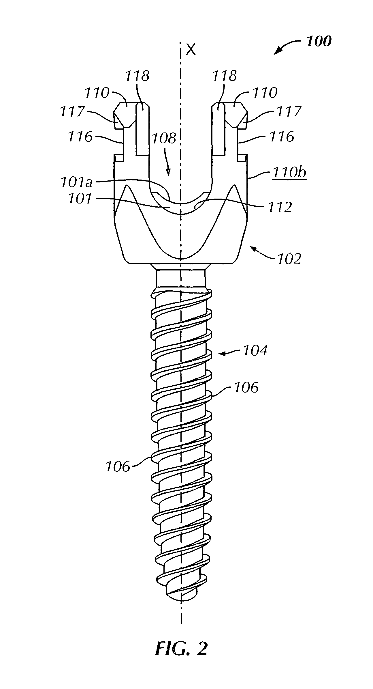
[0041]FIGS. 1, 2 and 11 show an exemplary bone anchor assembly, polyaxial bone screw or polyaxial pedicle screw 100 for use with an exemplary instrument set for minimally invasive spine surgery includes a body 102, a locking cap or...


PUM


Abstract

A minimally invasive system includes a bone screw and a tissue retractor having distal and proximal end portions and a partial pathway therebetween. The tissue retractor is removably couplable to the bone screw. An instrument has distal and proximal end portions and a hollow cavity and is removably couplable to the tissue retractor. A drive shaft has a diameter less than a diameter of the hollow cavity and is rotatable with respect to the instrument. A counter-torque handle has gripping and an interlock end portions with an instrument interface releasably positioned within the hollow cavity at the proximal end portion thereof and rotatably fixed thereto in an assembled configuration. The interlock end portion also includes an open-ended slot having a width greater than the drive shaft diameter such that the counter-torque handle is movable to and from the assembled configuration while the drive shaft is within the hollow cavity.

Description

BACKGROUND[0001]Retractors provide a surgeon with an access portal or pathway to a surgical site, for example during spine surgeries such as discectomies, laminectomies, facectomies, interbody fusions, pedicle screw fixation and similar procedures. Traditional spine surgeries were conducted utilizing an open procedure resulting in a relatively large incision, disruption or resection of significant soft tissue and long recovery times for patients. Minimally invasive techniques have become increasingly popular, particularly for spine surgeries, wherein relatively small incisions and surgical pathways are utilized to perform surgical procedures on a patient, generally resulting in a smaller incision or several relatively small incisions, less retraction and resection of soft tissue and shorter recovery times for patients in comparison to open procedures. Minimally invasive procedures are, in certain circumstances, able to obtain comparable or improved long term surgical outcomes in com...

Claims


Application Information

Patent Timeline
Patent Type & Authority Patents(United States)
IPC IPC(8): A61B17/70A61B17/58
CPCA61B17/7074A61B17/7079A61B17/7082A61B17/7086A61B17/7091A61B17/0218A61B17/7037A61B19/0271A61B2017/0046A61B50/33A61B17/025A61B17/7077A61B2017/0256
Inventor PETERSON, JOSEPHSOLITARIO, JR., RALPH
Owner DEPUY SYNTHES PROD INC
Learn More