Scalable silicon photonic multiplexers and demultiplexers

a photonic multiplexer and silicon technology, applied in multiplex communication, instruments, optical elements, etc., can solve the problems of increasing the bending loss, difficult to implement dwdm links on silicon, and not desirable for area-sensitive intra-chip applications, so as to reduce the associated tuning range of ring-resonator modulators

Active Publication Date: 2013-09-10
ORACLE INT CORP
View PDF1 Cites 17 Cited by
  • Summary
  • Abstract
  • Description
  • Claims
  • Application Information

AI Technical Summary

Benefits of technology

[0014]In some embodiments, the ring resonators have a common design with periodic optical resonances, and different optical channels are associated with different orders of the optical resonances of the ring resonators. Alternatively, the ring resonators may have different sizes so that optical resonances of the ring resonators are separated by a wavelength spacing between the optical channels, thereby reducing an associated tuning range of the ring resonators.
[0020]In some embodiments, the ring-resonator modulators have a common design with periodic optical resonances, and different optical channels are associated with different orders of the optical resonances of the ring-resonator modulators. Alternatively, the ring-resonator modulators may have different sizes so that optical resonances of the ring-resonator modulators are separated by a wavelength spacing between the optical channels, thereby reducing an associated tuning range of the ring-resonator modulators.

Problems solved by technology

However, it has been difficult to implement DWDM links on silicon because of the challenges involved in implementing certain optical components, such as an optical multiplexer / demultiplexer.
However, an optical multiplexer / demultiplexer based on AWG device, an Echelle-grating device or a Mach-Zehnder-based interleaver typically is large, which is not desirable for area-sensitive intra-chip applications.
However, decreasing the radius of a ring resonator typically increases the bending loss, with a commensurate impact on the insertion loss and the Q of the add / drop filter.
Such large temperature cycling can adversely impact the reliability of the ring resonator.
As a consequence, the FSR of a ring-resonator-based add / drop filter is currently constrained, which can limit the ability to scale the number of optical channels in a DWDM link.
However, such a wavelength-selective coupler typically works well for large bandwidths and has high losses for small bandwidths.
As a consequence, a wavelength-selective coupler is often impractical as an add / drop filter in a DWDM link that includes many closely spaced optical channels.
Thus, existing coupled-waveguide grating devices also limit the ability to scale the number of optical channels in a DWDM link.

Method used


Image

  • Scalable silicon photonic multiplexers and demultiplexers
  • Scalable silicon photonic multiplexers and demultiplexers
  • Scalable silicon photonic multiplexers and demultiplexers

Examples


Embodiment Construction

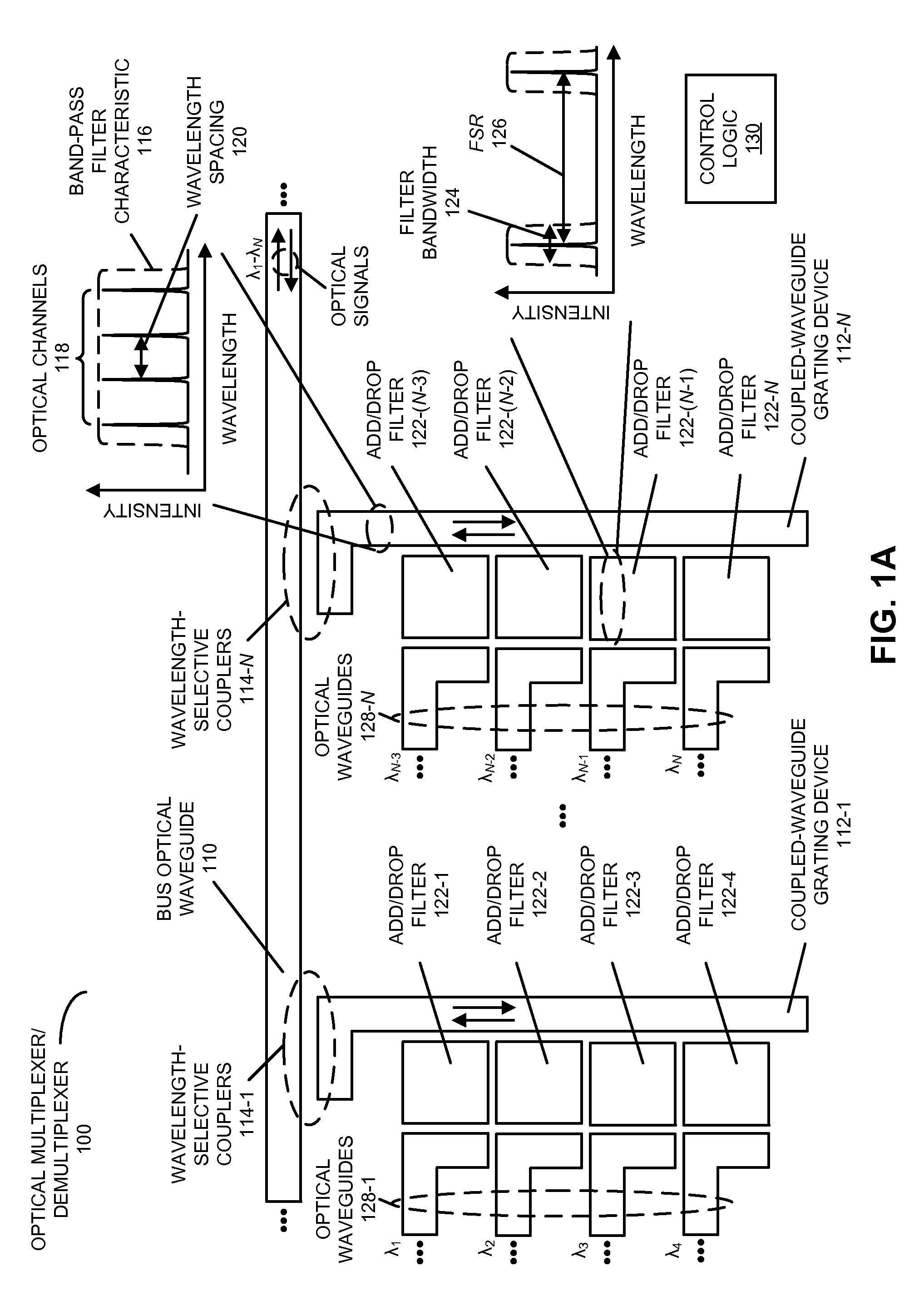
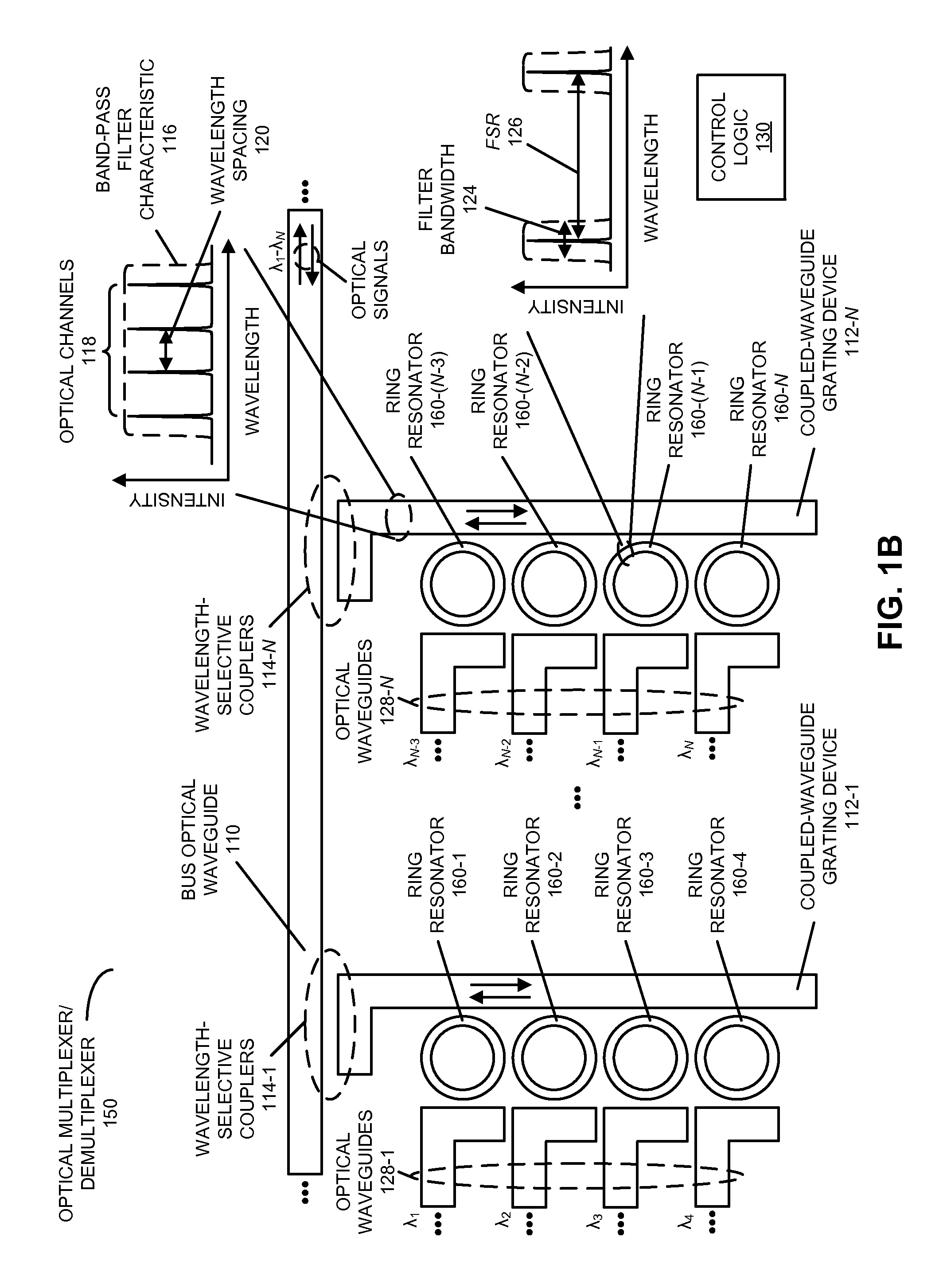
[0033]Embodiments of an optical multiplexer / demultiplexer, an optical modulator, a system that includes the optical multiplexer / demultiplexer and / or the optical modulator, a technique for multiplexing optical signals, and a technique for modulating optical signals are described. In the optical multiplexer / demultiplexer, multiple coupled-waveguide grating devices are optically coupled to a bus optical waveguide. A given coupled-waveguide grating device has a band-pass filter characteristic that encompasses multiple optical channels, thereby providing coarse optical filtering. Moreover, the optical multiplexer / demultiplexer includes multiple add / drop filters (such as ring resonators) that optically couple to the coupled-waveguide grating devices. A given add / drop filter has a filter bandwidth corresponding to a given optical channel, thereby providing fine optical filtering. Furthermore, the band-pass filter characteristic of the given coupled-waveguide grating device is approximately...


PUM


Abstract

An optical multiplexer / demultiplexer is described. In this optical multiplexer / demultiplexer, multiple coupled-waveguide grating devices are optically coupled to a bus optical waveguide. A given coupled-waveguide grating device has a band-pass filter characteristic that encompasses multiple optical channels, thereby providing coarse optical filtering. Moreover, the optical multiplexer / demultiplexer includes multiple add / drop filters (such as ring resonators) that optically couple to the coupled-waveguide grating devices. A given add / drop filter has a filter bandwidth corresponding to a given optical channel, thereby providing fine optical filtering. Furthermore, the band-pass filter characteristic of the given coupled-waveguide grating device is approximately equal to or less than a free spectral range (FSR) of the given add / drop filter.

Description

GOVERNMENT LICENSE RIGHTS[0001]The United States Government has a paid-up license in this invention and the right in limited circumstances to require the patent owner to license others on reasonable terms as provided for by the terms of Agreement No. HR0011-08-9-0001 awarded by the Defense Advanced Research Projects Administration.BACKGROUND[0002]1. Field[0003]The present disclosure relates to techniques for communicating optical signals. More specifically, the present disclosure relates to an optical multiplexer / demultiplexer and an optical modulator which include coupled-waveguide grating devices and add / drop filters that, respectively, provide coarse and fine optical filtering.[0004]2. Related Art[0005]Silicon photonics is a promising technology that can be used to provide high-performance, chip-scale communication networks with low cost. Unlike on-chip electrical interconnects in which multiple metal layers are used to transport electrical signals, silicon-photonic interconnects...

Claims


Application Information

Patent Timeline
Patent Type & Authority Patents(United States)
IPC IPC(8): G02B6/28H04J14/02
CPCG02B6/12007G02B6/29382G02B2006/12147H04J14/0201
Inventor ZHENG, XUEZHEKRISHNAMOORTHY, ASHOK V.FAINMAN, YESHAIAHU
Owner ORACLE INT CORP
Why Eureka
Try Eureka