A dynamic tuning device and tuning method for receiving end of wireless power transmission equipment

A wireless energy transmission and tuning device technology, applied in the direction of circuit devices, electrical components, etc., can solve the problems of reducing the transmission power and efficiency of the wireless energy transmission system, changes in the parameters of the wireless energy transmission system, and the tuning device cannot be tuned accurately in real time. Achieve the effects of easy promotion, improved transmission power and efficiency, and easy integration

Active Publication Date: 2016-03-02
SOUTHWEST JIAOTONG UNIV
View PDF3 Cites 0 Cited by
  • Summary
  • Abstract
  • Description
  • Claims
  • Application Information

AI Technical Summary

Problems solved by technology

[0005] However, most of the existing tuning devices at the receiving end are based on impedance measurement to change the number of switching capacitors for dynamic compensation to realize the tuning of the leakage inductance of the receiving end coil of the wireless energy transmission system; however, due to factors such as changes in the receiving end coil leakage inductance, its impedance It is difficult to measure in real time and accurately, so that the parameters of the wireless energy transfer system change, which in turn leads to changes in the resonance frequency between the sending end and the receiving end. power and efficiency

Method used


Image

  • A dynamic tuning device and tuning method for receiving end of wireless power transmission equipment
  • A dynamic tuning device and tuning method for receiving end of wireless power transmission equipment
  • A dynamic tuning device and tuning method for receiving end of wireless power transmission equipment

Examples


Embodiment

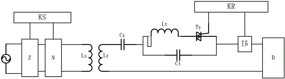
[0028] figure 1 It is shown that a specific embodiment of the present invention is a dynamic tuning device at the receiving end of a wireless power transmission device, which is characterized in that:

[0029] A compensation capacitor Cr, a phase-controlled inductance-capacitor parallel circuit, and a current sensor IR are sequentially connected between the receiving coil Lr and the load D in the receiving end of the wireless power transmission device; among them, the phase-controlled inductance-capacitor parallel circuit is composed of: inductance Lt and bidirectional The thyristor Ty is connected in parallel with the capacitor Ct after being connected in series; the control terminal of the bidirectional thyristor Ty and the output terminal of the current sensor IR are both connected with the tuning controller KR.

[0030] The method of using the dynamic tuning device in this example to tune the wireless power transmission equipment, the steps are:

[0031] A. Initially, the...


PUM


Abstract

The invention discloses a device and method for dynamic tuning of a receiving end of a wireless power transmission device. The device is composed of a compensation capacitor (Cr), a phase control inductance capacitance parallel circuit and a current sensor (IR), wherein the compensation capacitor (Cr), the phase control inductance capacitance parallel circuit and the current sensor (IR) are connected between a receiving coil (Lr) in the receiving end of the wireless power transmission device and a load (D) in sequence. According to the phase control inductance capacitance parallel circuit, an inductor (Lt) is connected with a bidirectional thyristor (Ty) in series and then connected with a capacitor (Ct) in parallel; the control end of the bidirectional thyristor (Ty) and the output end of the current sensor (IR) are both connected with a tuning controller (KR). By the adoption of the device and method for dynamic tuning of the receiving end of the wireless power transmission device, the receiving end can keep operating at the maximum current effect value; namely, a receiving end circuit is closer to the complete resonance state, the active power of the receiving end is improved, and therefore the transmission power and the efficiency of the wireless power transmission device are improved.

Description

technical field [0001] The invention belongs to the technical field of wireless power transmission, in particular to a dynamic tuning device and a tuning method thereof in inductive coupling wireless power transmission equipment. Background technique [0002] Since the 21st century, the basic theoretical research of wireless power transmission and the industrial application of related technologies have become the current research hotspots, which have attracted the close attention of many domestic and foreign scholars and industrial circles. The application of wireless energy transmission technology is as small as electric toothbrush and mobile phone charging, as large as electric vehicle wireless charging pile and rail transit wireless power supply system, and it is gradually developing towards high-power applications. [0003] The inductive coupling wireless power transmission method is one of the most promising ones in the direction of high-power development among many wir...

Claims


Application Information

Patent Timeline
Patent Type & Authority Patents(China)
IPC IPC(8): H02J50/12
Inventor 麦瑞坤陆立文李勇何正友李砚玲
Owner SOUTHWEST JIAOTONG UNIV
Why Eureka
Try Eureka