
Millimeterwave tuners with external airline

Active Publication Date: 2021-05-11
TSIRONIS CHRISTOS
View PDF3 Cites 0 Cited by
  • Summary
  • Abstract
  • Description
  • Claims
  • Application Information

AI Technical Summary

Benefits of technology

The invention describes a new passive coaxial tuner structure that can reach the maximum possible reflection factor (tuning range) of a passive tuner and minimize insertion loss. This is achieved by creating an external airline (slabline) that is connected directly to the tuner and controls its movement using a new set of horizontal and vertical coordinates. The tuner calibration and impedance synthesis are also using the new set of coordinates. The invention allows for improved tuning performance and better high power device connection using a passive tuner.

Problems solved by technology

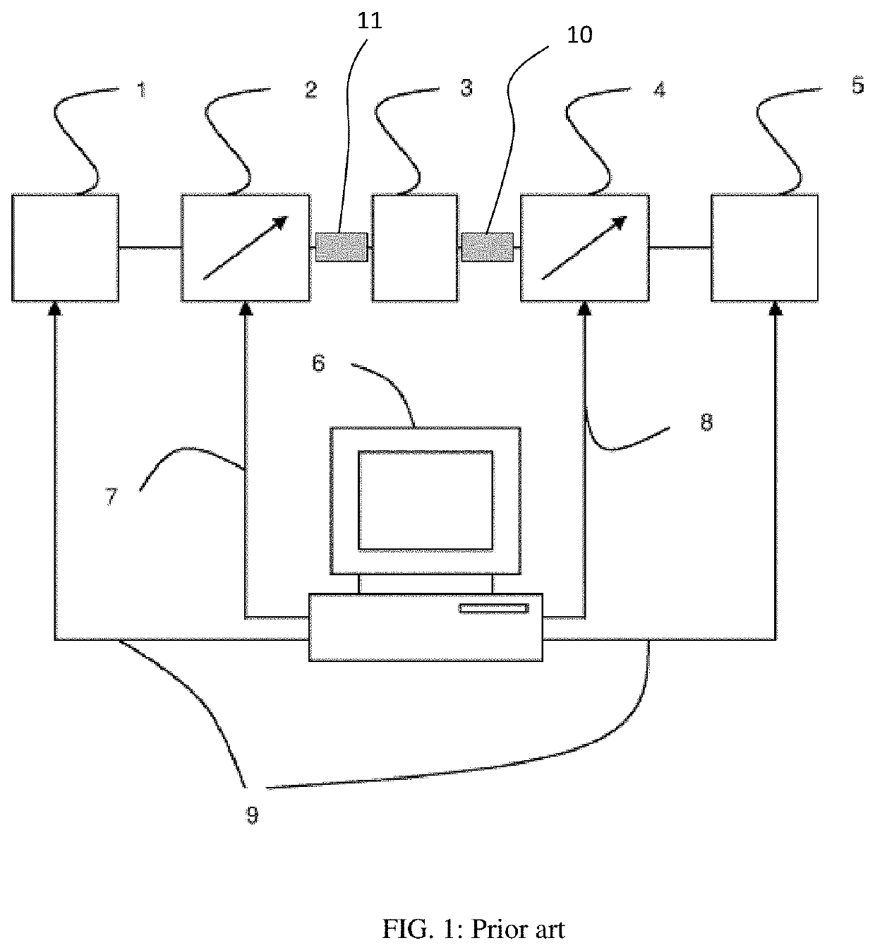
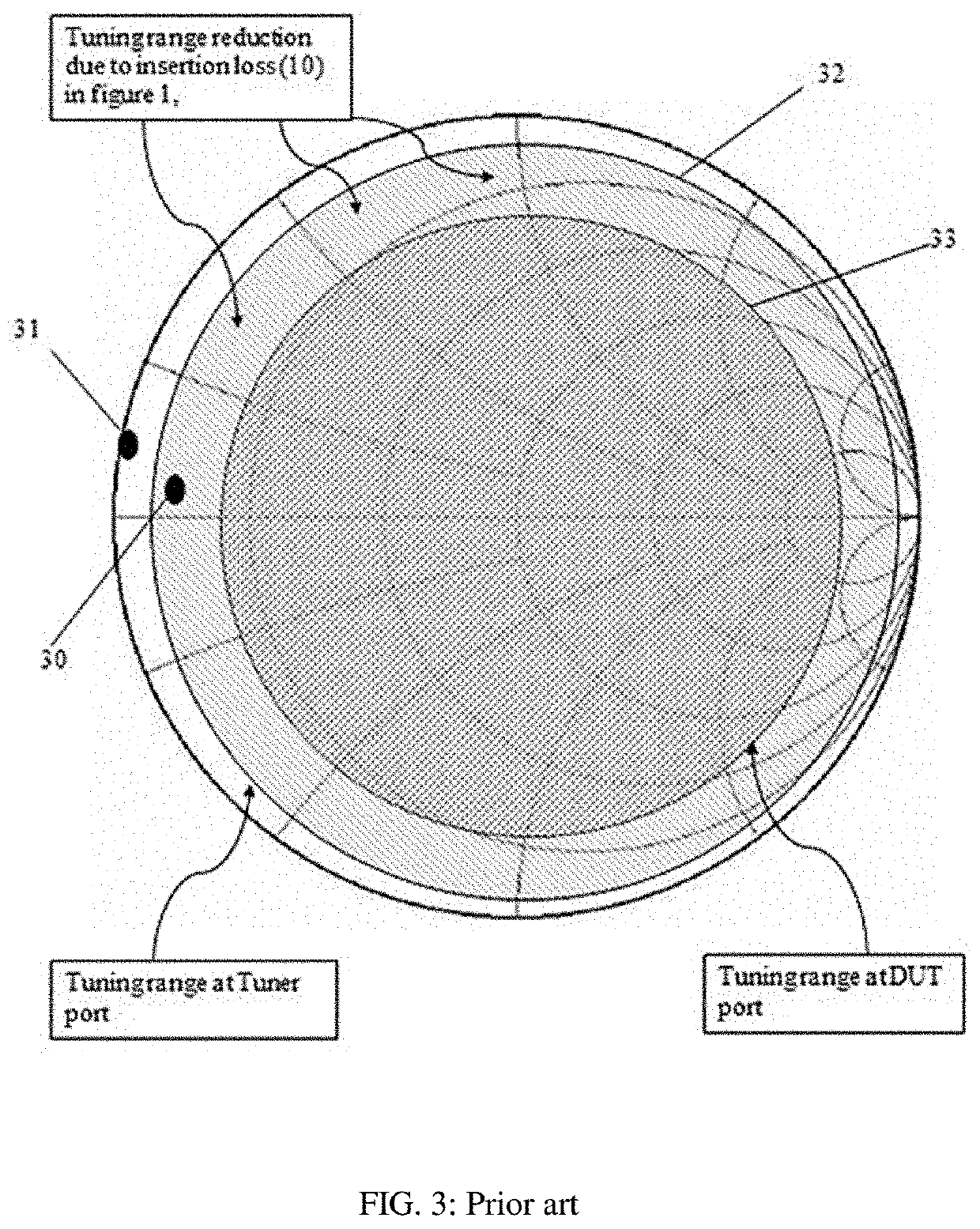
"d_n">A major issue with passive tuners is that the insertion loss shown in FIG. 1 (10, 11) and FIG. 9 between the tuner test port and the DUT reduces the tuning range (FIG. 3).
Realistically, high power devices having internal impedance in area (31) cannot be reached at all using passive tuners.

Method used


Image

  • Millimeterwave tuners with external airline
  • Millimeterwave tuners with external airline
  • Millimeterwave tuners with external airline

Examples


Embodiment Construction

"d_n">[0024]The new tuner structure is shown in FIG. 5 through 8. Since the tuner is designed for frequencies above 18 GHz, the horizontal travel of the tuning probe is restricted to XMAX=½*λ(18 GHz)≈8.34 mm; this means the whole horizontal remotely controlled movement can be accommodated by the sloped section of the external parallel plate airline (slabline); therefore we can use a short slabline and mount it outside the tuner body, aligned with and directly attached to the wafer probe. This eliminates two major problems: (a) the insertion loss is minimized and (b) a short slabline is easier to manufacture. But, there are two main difficulties of this configuration that require innovative solutions. The first one is to handle the effect of the rotational momentum created by the friction of the probe inside the slabline during horizontal and vertical movement, on the stability and repeatability of the carriage, which slides on the rail (508). This is being overcome by compensating s...


PUM


Abstract

A passive slide screw load pull tuner structure can be used on-wafer, in millimeter-wave frequencies from 20 to 110 GHz. It uses a short external (not extended) slabline, mounted sloped and allowing direct contact with the wafer probe, thus permitting the tuning probe to come as close to the wafer probe as physically possible; this minimizes the insertion loss between tuner and DUT and, thus, generates the maximum possible tuning range of a passive electro-mechanical impedance tuner.

Description

PRIORITY CLAIM[0001]This application claims priority on provisional application No. 62 / 550,336, filed on Aug. 25, 2017, titled: “MILLIMETERWAVE TUNERS WITH EXTERNAL AIRLINE”.CROSS-REFERENCE TO RELATED ARTICLES[0002]1. “Load Pull” [online] Wikipedia, [Retrieved on 2017 Aug. 24]. Retrieved from Internet <URL: https: / / en.wikipedia.org / wiki / Load_pull>.[0003]2. “Computer Controlled Microwave Tuner, CCMT”, Product Note 41, Focus Microwaves Inc. 1998, pages 2-4.[0004]3. “Standing wave ratio” [online], Wikipedia, [Retrieved on 2017 Feb. 3]. Retrieved from Internet <URL: https: / / en.wikipedia.org / wiki / Standing_wave_ratio>.[0005]4. Tsironis, U.S. Pat. No. 6,674,293, “Adaptable pre-matched tuner system and method”.[0006]5. “MPT, a universal Multi-Purpose Tuner”, Product Note 79, Focus Microwaves Inc., October 2004.BACKGROUND OF THE INVENTION[0007]This invention relates to millimeter-wave load and source pull testing of medium and high power transistors and amplifiers using remotely ...

Claims


Application Information

Patent Timeline
IPC IPC(8): G01R1/067G01R31/26G01R27/06G01R31/28
CPCG01R1/06772G01R27/06G01R31/2601G01R31/2831G01R27/32G01R31/2822H01P5/04
Inventor TSIRONIS, CHRISTOS
Owner TSIRONIS CHRISTOS
Learn More