Optical terminus keying

Active Publication Date: 2005-08-02
ITT MFG ENTERPRISES INC
View PDF17 Cites 9 Cited by
  • Summary
  • Abstract
  • Description
  • Claims
  • Application Information

AI Technical Summary

Benefits of technology

[0004]In accordance with one embodiment of the present invention, an optical fiber connector is provided, which includes a housing having a plurality of terminus-receiving passages and optical fiber terminus assemblies that fit into the passages, which minimizes insertion loss. The connector includes means for fixing the rotational orientation of each terminus assembly about the corresponding passage axis, in a construction that allows removal and reinstallation of a terminus assembly at the same rotational orientation, and with close spacing between the passages. An index sleeve with a noncircular periphery is provided, that can be installed on the terminus body at any relative rotational position. In addition, each terminus-receiving passage of the housing is provided with an indexing passage portion that is noncircular and that receives the index sleeve at only one rotational position of the index sleeve about the passage axis.

Problems solved by technology

This results in an insertion loss, which is the loss of light intensity due to the light having to pass between the tips of two imperfectly abutting fibers.
For systems where the light is polarized, a rotational position angled even a few degrees from the position of minimum insertion loss, can result in a significantly greater insertion loss than at the best position.

Method used


Image

  • Optical terminus keying
  • Optical terminus keying
  • Optical terminus keying

Examples


Embodiment Construction

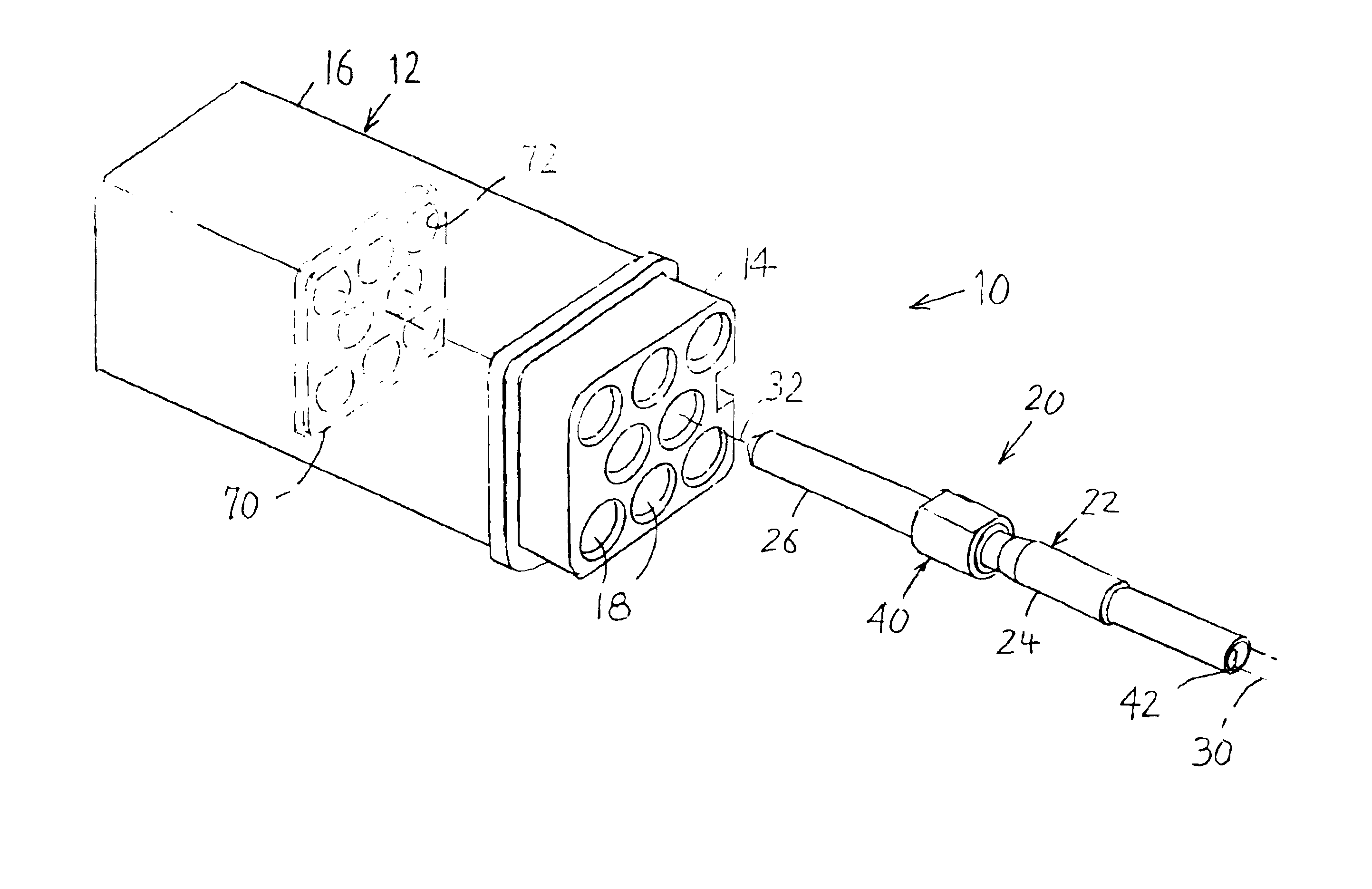
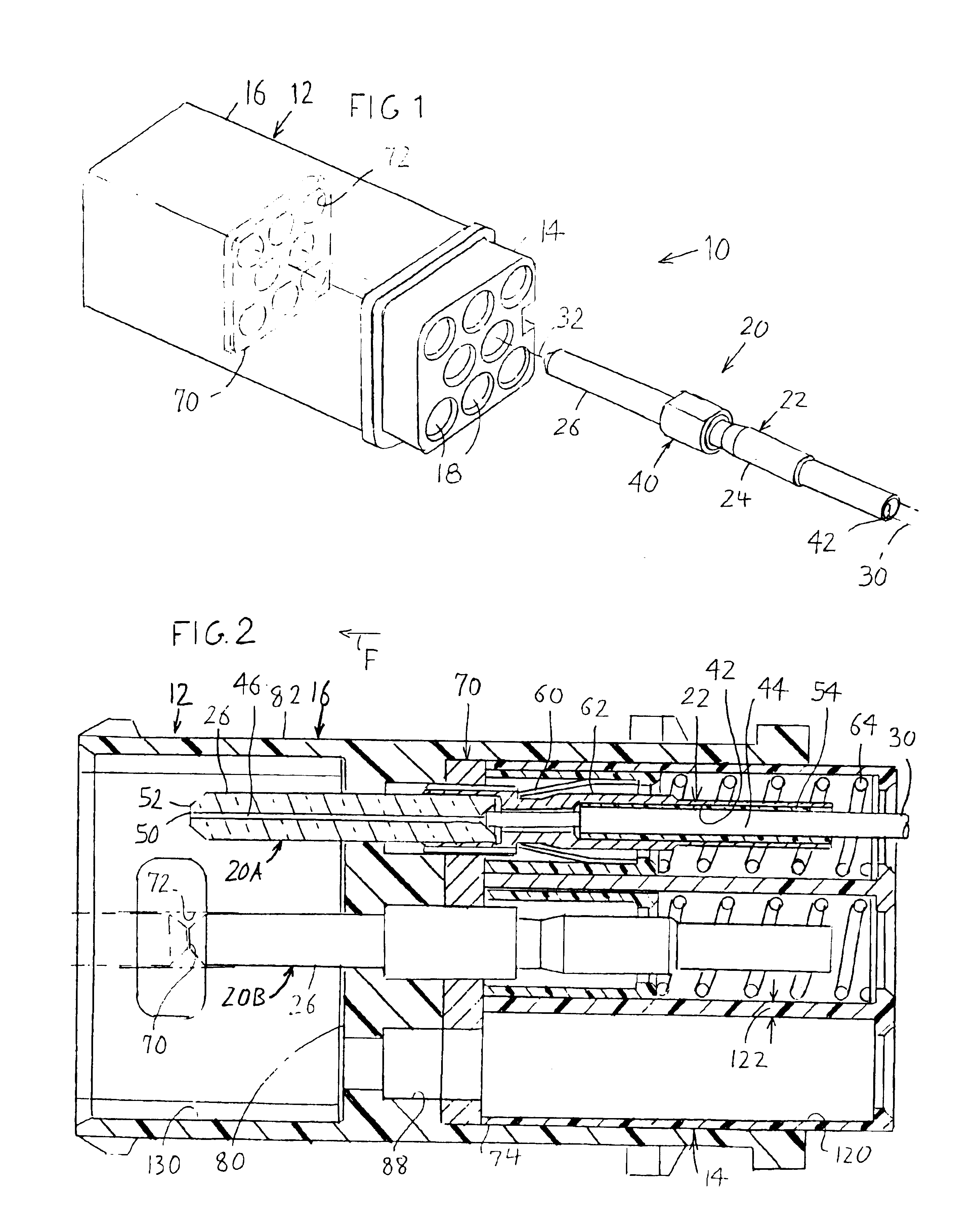
[0012]FIG. 1 illustrates an optical fiber connector 10 of the present invention, which includes a housing 12 with inner and outer housing parts 14, 16. The housing forms terminus-receiving passages 18 with portions in each housing part. An optical fiber terminus assembly 20 can be installed in any one of the passages. The assembly 20 includes a terminus 22 with a body 24 and a ferrule 26, and a stripped front end of an optic fiber cable indicated in phantom lines at 30. The connector also includes an index sleeve 40 which is mounted on a front portion of the terminus body 24, and which determines the rotational position of the terminus assembly 20 about its axis 32.

[0013]FIG. 2 shows two terminus assemblies 20A, 20B, with assembly 20A being shown in section and assembly 20B being shown in side elevation. The terminus 22 of the assembly 20A has a bore 42 that receives the stripped front portion 44 of the cable 30. The entire cable includes an outer jacket and a strength member within...


PUM


Abstract

An optical fiber connector in which a terminus assembly (20) can be keyed so it is always installed in a predetermined rotational position about the axis of a terminus-receiving passage (18) of a housing (12). When a terminus rotational position is found that results in minimal insertion loss, a noncircular index sleeve (40) is placed around the terminus body (24) and fixed thereto. An indexing plate (70) is installed in the connector housing, with indexing passage portions (72) that receive the index sleeve at only a single rotational position of the indexing sleeve about the passage axis.

Description

BACKGROUND OF THE INVENTION[0001]Optical fibers are commonly coupled to one another by attaching a terminus to the stripped end of each optic fiber cable. The tip of each optic fiber is lapped flush with the tip of a ferrule of the terminus. The tips of the ferrules and fibers are aligned within a precision alignment sleeve so the tips of the two fibers abut one another. In practice, the tips of the fibers are slightly eccentric to the axis of the ferrules (e.g. by perhaps 3 microns for a single mode fiber of 9 microns diameter), and the tips lie in planes that are not exactly perpendicular to the ferrule axes. This results in an insertion loss, which is the loss of light intensity due to the light having to pass between the tips of two imperfectly abutting fibers.[0002]The insertion loss can be reduced by rotating one terminus and its corresponding optical fiber, to different positions about the terminus axis and measuring the insertion loss at each position. For nonpolarized syste...

Claims


Application Information

Patent Timeline
IPC IPC(8): G02B6/38G02B6/40
CPCG02B6/3812G02B6/3834G02B6/3851G02B6/3869G02B6/3878
Inventor BETKER, JAY BRIANADAMS, TERRY LEE
Owner ITT MFG ENTERPRISES INC
Why Eureka
Try Eureka