Welded rotor of a gas turbine engine compressor

a gas turbine engine and compressor technology, applied in the direction of machines/engines, wind motors with perpendicular air flow, waterborne vessels, etc., can solve the problems of more difficult realization of internal cooling via holes, and achieve the effects of reducing production costs, reducing manufacturing costs, and increasing heat discharg

Inactive Publication Date: 2013-08-27
ANSALDO ENERGIA SWITZERLAND AG
View PDF20 Cites 3 Cited by
  • Summary
  • Abstract
  • Description
  • Claims
  • Application Information

AI Technical Summary

Benefits of technology

[0014]The recess is expediently applied to the last rotor disk which is subjected to the highest temperatures. The coolable recess together with the abutment joint of the rotor disks in the central region particularly ensures an increased heat discharge from the middle region of the rotor towards the rotor surface.
[0016]The rotor, in the region of the highest temperatures, has two or more rotor disks which in comparison to the rotor disks of the prior art are of a smaller, i.e. less thick, design. However, they extend over at least three blade stages. On account of their smaller size, these are simpler to produce. In particular, their forgeability is improved and the achievable degree of deformation is increased.
[0017]Moreover, the individual rotor disks are simpler to test during the forging process, since because of the smaller thickness of the disks the path length of sound waves during testing is shortened and consequently measuring results with higher resolution can be achieved.
[0018]The abutment joint over the radially inner central region of the last two rotor disks in the flow direction can bring about a heat flow from the central region of the rotor to the radially outer surface of the rotor, where it can be discharged via the recess. As a result, the problem of excessive heating of the rotor at the last point of the rotor in the flow direction, which occurs particularly in the case of gas turbine compressors, is solved. The material temperature of the rotor during operation can consequently be kept below a predetermined level and therefore the service life of the rotor can be increased. The construction of the coolable rotor according to the invention is most effective at the last point of the rotor which is also subjected to the highest temperatures.
[0021]By using a heat-conducting constituent, the heat flow from the middle of the rotor disk, that is to say from the region around the rotational axis and from the first to the second abutment-joined rotor disks, to the outer surface of the rotor is of further benefit and the anticipated service life of the rotor is further increased.
[0025]As a result of the weld shrinkage, a residual compressive stress is created, enabling an increased service life of the rotor.

Problems solved by technology

The cooling methods for bolted rotors can be used in the case of welded rotors only to a limited extent because the rotor disks in the case of welded rotors are more solid in comparison to bolted rotors and internal cooling via holes would be more difficult to realize.

Method used


Image

  • Welded rotor of a gas turbine engine compressor
  • Welded rotor of a gas turbine engine compressor
  • Welded rotor of a gas turbine engine compressor

Examples


Embodiment Construction

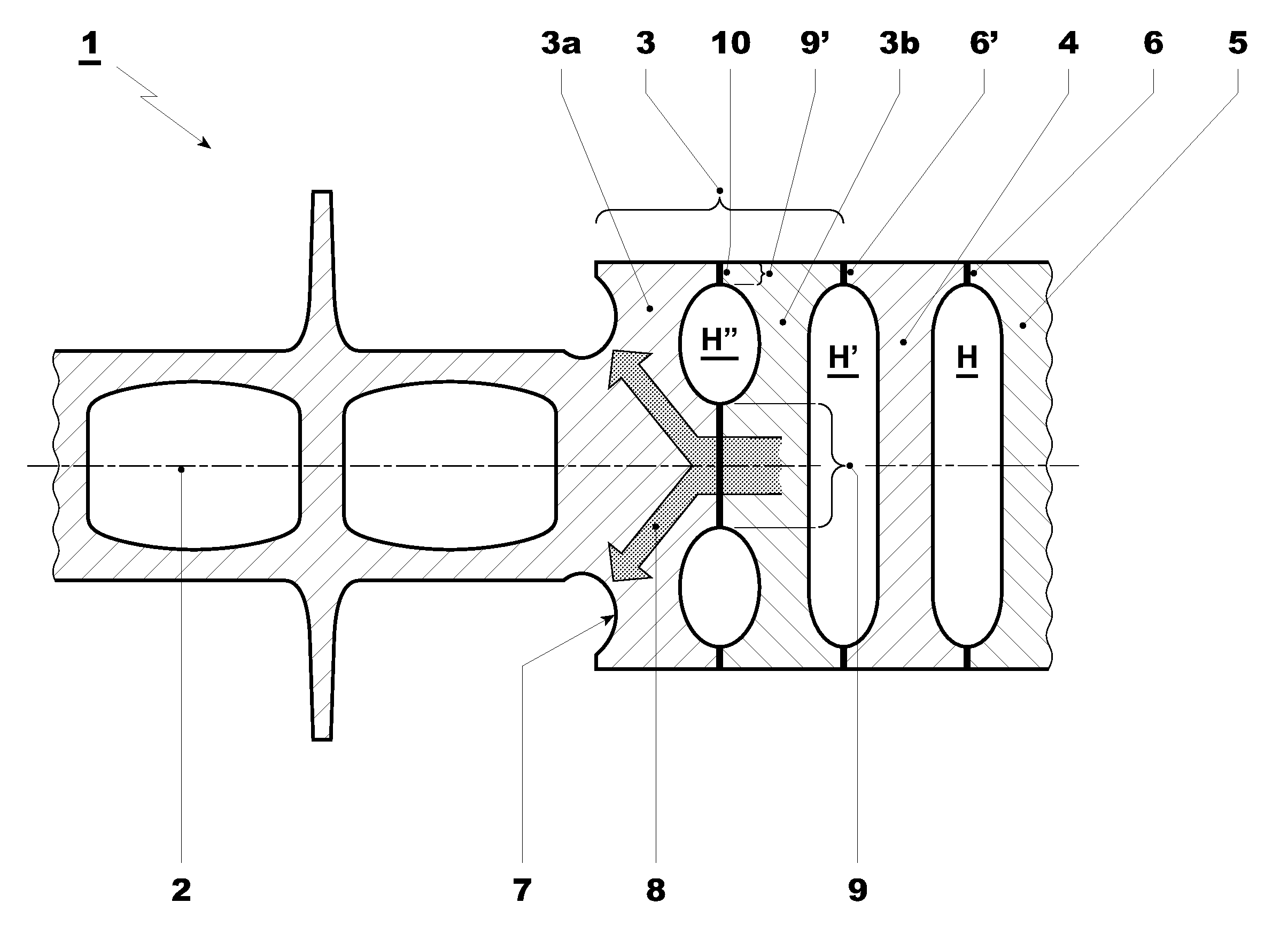
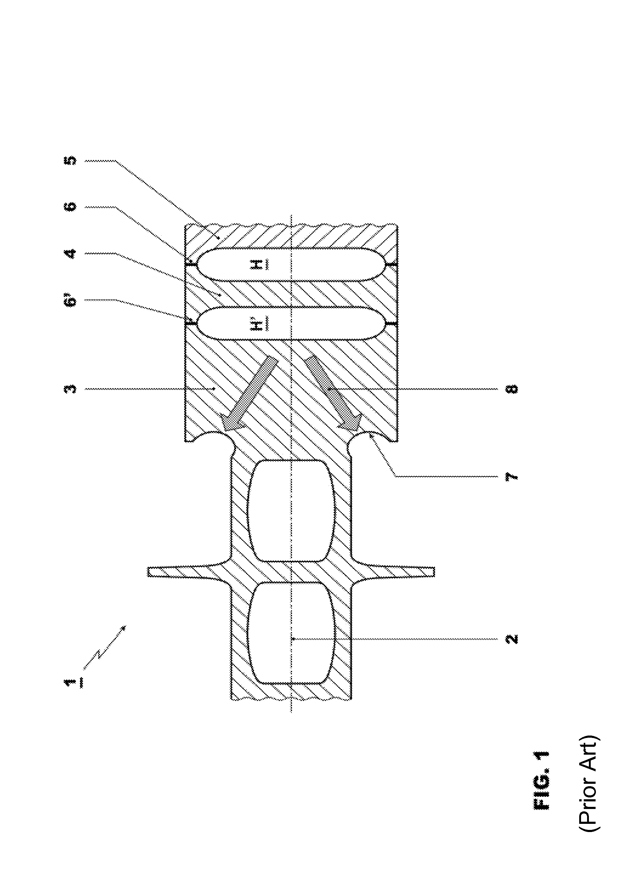
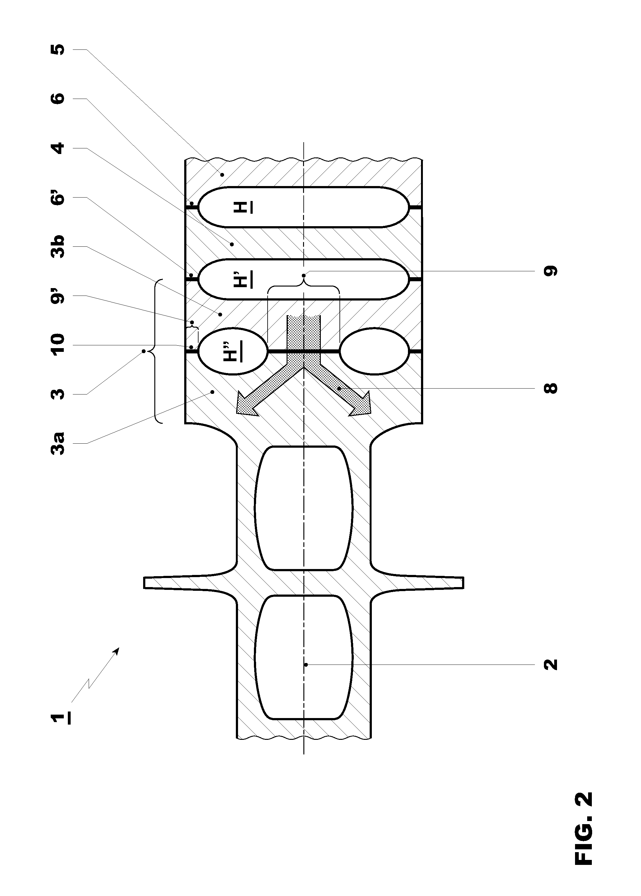
[0034]FIG. 2 shows in longitudinal cross section a gas turbine compressor rotor 1 with a rotor axis 2. The rotor 1 comprises a multiplicity of rotor disks, of which only rotor disks 3, 4 and 5 are shown in the figure. The rotor disks are constructed in each case so that they can accommodate at least three blade stages of the compressor. As a result, they differ from rotor disks of a rotor of a so-called “laminar” design which extend over only one blade stage. In their middle, rotor disks 4 and 5 have a recess in each case which together form a cavity H after the joining together of the disks. The rotor disks 4 and 5 are interconnected by means of a weld seam 6 between the cavity H and the radially outer surface of the disks 4 and 5. The rotor disk 3 of the rotor of the prior art is realized according to the invention by two individual rotor disks 3a and 3b which in comparison are less solidly formed. In the depicted example, the rotor disks 3a and 3b are the rotor disks of a compres...


PUM

PropertyMeasurementUnit
heat-conductingaaaaaaaaaa
temperaturesaaaaaaaaaa
weld shrinkageaaaaaaaaaa

Abstract

A rotor (1) of a gas turbine compressor comprises a multiplicity of welded-together rotor disks (3a, 3b, 4, 5), of which two or more rotor disks (3a, 3b), in a radially outer region (9′), are welded together, and, in a radially inner central region (9), are abutment-joined together. Via the abutment-joining of two rotor disks (3a, 3b), a heat flow (8) radially outward from the center of the rotor (1) is achieved so that the material temperature of the rotor (1) can be kept below a predetermined level during operation. As a result, the service life of the rotor (1) can be increased. In one embodiment, one rotor disk (3a), on its surface, additionally has a recess (7) which can be cooled from outside. The rotor disks (3a, 3b) according to the invention, which are welded and abutment-joined together, can especially be used at the last point in the flow direction of the compressor.

Description

RELATED APPLICATIONS[0001]The present application is a Continuation of PCT Application No. PCT / EP2010 / 066501, filed Oct. 29, 2010, which claims priority to Swiss Patent application number 01699 / 09, filed Nov. 4, 2009, the entire contents of which are hereby incorporated by reference.TECHNICAL FIELD[0002]The present invention refers to welded rotors for gas turbine compressors, and also to a method for their production.BACKGROUND OF THE INVENTION[0003]Rotors for gas turbines usually comprise a plurality of disks which are either joined together by means of bolted connections or are welded together. In order to avoid overheating during operation and consequently to avoid reduction of the service life of the rotors which is brought about, the rotors are actively cooled. In this case, there is a difference between cooling methods for rotors which are connected by bolts and for welded rotors. The cooling methods for bolted rotors can be used in the case of welded rotors only to a limited...

Claims


Application Information

Patent Timeline
Patent Type & Authority Patents(United States)
IPC IPC(8): F04D29/044B21K25/00
CPCF01D5/063F01D5/082Y10T29/49321Y10T29/4932Y10T29/49323F05D2230/232
Inventor PAULI, ERNSTKRAMER, THOMASKIEWEL, HOLGER
Owner ANSALDO ENERGIA SWITZERLAND AG
Why Eureka
Try Eureka