Vacuum demand valve

a demand valve and vacuum technology, applied in the direction of valve operating means/release devices, instruments, process and machine control, etc., can solve the problems of inhalation of gas, potential health hazards, and undesirable inhalation of gas by clinicians in the area, so as to avoid significant resistance to exhalation

Inactive Publication Date: 2013-08-27
LINDE AG
View PDF15 Cites 0 Cited by
  • Summary
  • Abstract
  • Description
  • Claims
  • Application Information

AI Technical Summary

Benefits of technology

[0024]It will be understood that a patient has a breathing cycle comprising an inhalation stage and an exhalation stage, and wherein the diaphragm is preferably sized such that the predetermined pressure in the housing at which the sealing member opens the housing outlet is exceeded only a short time after the commencement of the exhalation stage to avoid significant resistance to exhalation being applied to the patient by the demand valve.

Problems solved by technology

In hospitals and surgeries, where a range of anaesthetic gases are used, there is a problem in dealing with the exhaled gas, such as N2O.
Not all inhaled anaesthetic gas is absorbed by the patient, and it is undesirable for the clinicians in the area to inhale the gases.
Although the levels are low, long term exposure may present potential health hazards.
The patient should not be able to re-breathe exhalation gases that have already been exhaled into the scavenger.
Thus, the device may use significantly more vacuum flow than needed for the patient, wasting valuable energy and causing a drain on the hospital vacuum system.
If a user forgets to turn the device on, then a patient may inadvertently exhale to atmosphere.
If a user forgets to turn off the device after use, there will be a constant drain on the hospital vacuum system.
This means that the scavenger is large relative to typical medical equipment such as a demand valve or a gas mixer and therefore it may occupy an undue amount of space, and be inconvenient to move.
Further, the size of the device and the amount of material used in its manufacture will result in a high cost high, even though the technology may be simple.
The constant flow of air into the vacuum system can cause a background noise, where the surge chamber can act as a sounding device, amplifying the sound, which can be a strain on the user and the patient.
Further, there is very limited indication that the scavenger is operating properly, as there are no moving parts to be observed.

Method used


Image

  • Vacuum demand valve
  • Vacuum demand valve
  • Vacuum demand valve

Examples


Embodiment Construction

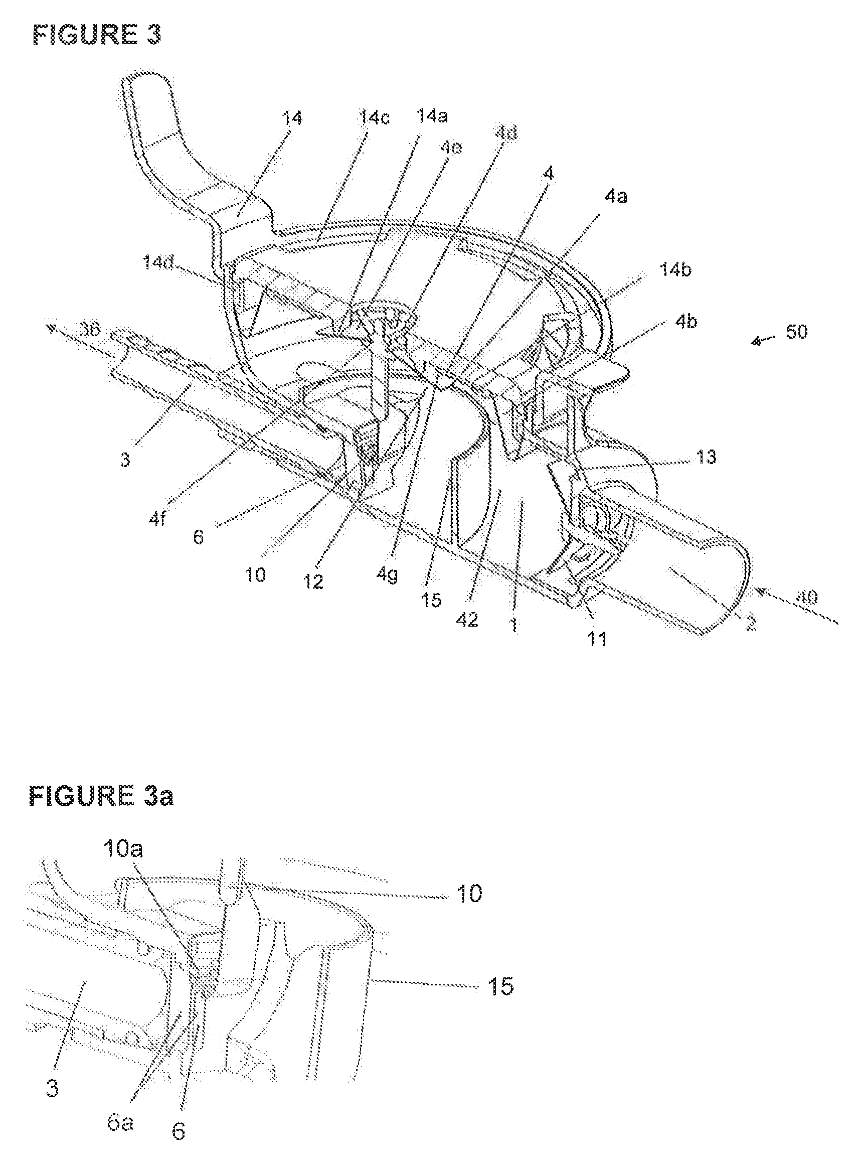
[0035]Referring to FIG. 8, a vacuum demand, or diaphragm, valve 30 is shown for use on the exhalation side of a breathing apparatus 32 for controlling the flow of exhalation gases from a patient 34 to a vacuum line 36. Known demand valves are connected to control the supply of compressed gas to a patient rather than to control the supply of exhaled gas to a vacuum.

[0036]A typical breathing apparatus may comprise a mask adapted to be placed over a nose and mouth of a patient for allowing a mixture of anaesthetic gases to be breathed in by a patient an exhaled along an exhalation line 40 to the demand valve 30. The vacuum line is connected to a source of vacuum, which is typically a hospital waste gas disposal system 38. Usually a hospital wall or ceiling has a vacuum port to which a vacuum line can be connected from the demand valve to the vacuum source the latter of which is located elsewhere in a hospital. In use of the arrangement shown in FIG. 8, a mixture of anaesthetic gases is...


PUM


Abstract

A vacuum demand valve for controlling flow of exhalation gases from a patient to a vacuum line. The demand valve comprises: a housing having a housing inlet that allows exhalation gases to flow into the housing from a patient, and a housing outlet that allows gases to flow from the housing into the vacuum line; a diaphragm having a flexible skirt and a rigid portion moveable in response to gas pressure in the housing; a sealing member connected to the rigid portion to engage the housing outlet to resist the flow of gases from the housing to the vacuum line. In a first condition, the vacuum line pressure causes the sealing member to engage the housing outlet and in a second condition a predetermined pressure of exhalation gases in the housing causes the sealing member to disengage from the housing outlet.

Description

CROSS REFERENCE TO RELATED APPLICATIONS[0001]This application claims priority from United Kingdom Patent Application Serial No. GB0916971.5 filed Sep. 29, 2009.FIELD OF INVENTION[0002]The present invention relates to a vacuum demand valve for use on the exhalation side of a breathing apparatus for controlling the flow of exhalation gases from a patient to a vacuum line, for example, a vacuum line connected to a vacuum source of a hospital waste gas disposal system.BACKGROUND OF THE INVENTION[0003]In hospitals and surgeries, where a range of anaesthetic gases are used, there is a problem in dealing with the exhaled gas, such as N2O. Not all inhaled anaesthetic gas is absorbed by the patient, and it is undesirable for the clinicians in the area to inhale the gases. Although the levels are low, long term exposure may present potential health hazards. Existing prior art scavengers are designed to dispose exhaled gases without allowing them to vent to atmosphere.[0004]In one prior art sy...

Claims


Application Information

Patent Timeline
Patent Type & Authority Patents(United States)
IPC IPC(8): A62B9/00F16K31/126A61M16/20
CPCA61M16/009A61M16/20A61M16/208A61M16/206Y10T137/2605Y10T137/0396Y10T137/2622
Inventor TATAREK, ANDREW RICHARD THOMASWEISZL, GUNTHER
Owner LINDE AG
Why Eureka
Try Eureka